A Software Model of the CIA6526
by pc64@compuserve.com (Wolfgang Lorenz)
Version 2.15, May 1997
This document is part of the Emulator Developers Kit (EDK) available at http://ourworld.compuserve.com/homepages/pc64/develop.htm. It describes the internal working of the CIA6526 from the standpoint of a software developer. It acts as an oversight to the source code which is provided as CIA6526.cpp and CIA6526.h. Time of Day (TOD) and Serial Data Register (SDR) haven't been implemented yet.
The CIA6526 contains two timers, A and B. Timer A can be set to either count ø2 (phi two) system clocks or rising edges of the CNT line. Bit 5 of the Control Register A at offset 0x0E selects the source for timer A.

Figure 1. Source for Timer A
In ø2 mode, the input of timer A is always 1. This means that the counter will be decremented with each system clock.
In CNT mode, the input must be synchronized with ø2. When there is a rising edge on the CNT line, the bit CountA0 in dwDelay is set to 1. At each system clock, dwDelay is shift left by one and the shift out bits are filled from dwFeed. Because dwFeed & CountA0 is always 0, a single 1 is shifted through the pipeline until it reaches CountA3, which will then decrement the counter.
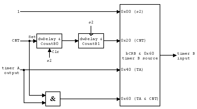
Timer B works similar but can also count underflows of timer A (cascaded mode). Bits 6 and 5 of the Control Register B at offset 0x0F select the source for timer B.

Figure 2. Source for Timer B
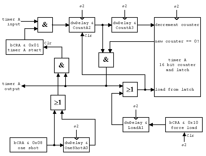
Each timer consists of a 16 bit counter and a 16 bit latch. Two clocks after bit 0 in the CRA has been set to 1, the timer will start counting from its current value back to zero. When the counter has reached zero, it is reloaded from the latch as soon as there is another clock waiting in the pipeline. In ø2 mode, this is always the case. This explains why you are reading zeros in cascaded mode only (2-2-2-1-1-1-0-0-2) but not in ø2 mode (2-1-2).

Figure 3. Layout of the Timer (both A and B)
Whenever the counter is reloaded from the latch, either by underflow or by setting the force load bit of the CRA to 1, the next clock will be removed from the pipeline. This explains why you are reading two successive values (2-1-2-2-1-2) in ø2 mode.
If the timer underflows and CRA bit 3 (one shot) is set or has been set in the clock before, then bit 0 of the CRA will be cleared. Because CountA2 has already been cleared by the underflow, the timer stops immediately.
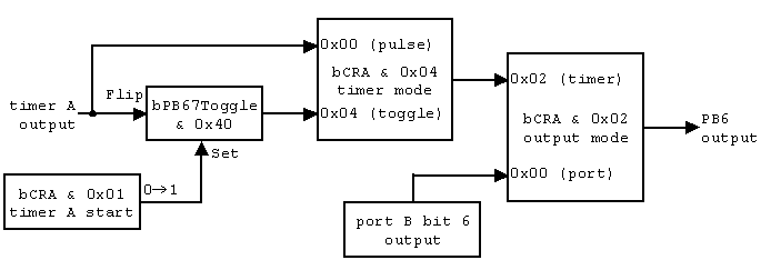
The bits 6 and 7 of port B can be programmed to reflect the output of the timers. This is done with bit 1 in the Control Registers A and B.

Figure 4. Timer Output to PB6 (Timer A) and PB7 (Timer B)
The normal output of a timer is a high pulse which lasts for one ø2 clock. By setting bit 3 of the CRA, PB6 will be toggled between high and low at each underflow. The toggle flip-flop is set on a rising edge of bit 0 in the CRA and is cleared on a system reset.
The output of the toggle flip-flop may also be used for the SDR. This hasn't been researched yet.
When a timer underflows, the corresponding bit in the Interrupt Control Register (ICR) will be set.

Figure 5. Interrupt Logic
When the bit in the Interrupt Mask Register (IMR) is also set, the CIA6526 will raise an interrupt with a delay of one ø2 clock. This interrupt can be prevented by reading the ICR at the time of the underflow. Once the interrupt flip-flop has been set, changing the condition in the IMR has no effect. Only reading the ICR will clear it.
The files CIA6526.cpp and CIA6526.h contain the current implementation of the CIA6526 in PC64Win. In order to verify that this model is correct, some test programs have been added to the C64 Emulator Test Suite.
Programs CIA1TB123 and CIA2TB123 - CIA timer B 1-3 cycles after writing CRB
The cycles 1-3 after STA DD0F cannot be measured with LDA DD06 because it takes 3 cycles to decode the LDAa. Executing the STA DD0F at DD03 lets the CPU read DD06 within one cycle.
#1 #2  DD06 sequence 1/2/3 (4)
---------------------------------
00 01  keep   keep   count  count
00 10  keep   load   keep   keep
00 11  keep   load   keep   count
01 11  count  load   keep   count
01 10  count  load   keep   keep
01 00  count  count  keep   keep
#1, #2 = values written to DD0F
Programs CIA1PB6 to CIA2PB7 - CIA timer output to PB6 and PB7
Checks 128 combinations of CRA/B in One Shot mode:
  old CRx bit 0 Start
      CRx bit 1 PBxOut
      CRx bit 2 PBxToggle
  new CRx bit 0 Start
      CRx bit 1 PBxOut
      CRx bit 2 PBxToggle
      CRx bit 4 Force Load
The resulting PB6/7 bit is:
  0 if new PBxToggle is 0
  1 if new PBxToggle is 1
  - (undetermined) if PBxOut is 0
Old values do not influence the result. Start and Force Load don't either.
Next, the programs test if PBx is toggled to 0 on the first underflow and that neither writing CRx except bit 0 nor Timer Hi/Lo will set it back to 1. The only source which is able to reset the toggle line is a rising edge on the Start bit 0 of CRx.
Another test verifies that the toggle line is independent from PBxOut and PBxToggle. Changing these two bits will have no effect on switching the toggle flip flop when the timer underflows.
The last test checks for the correct timing in Pulse and Toggle Mode.
Program CIA1TAB - TA, TB, PB67 and ICR in cascaded mode
Both latches are set to 2. TA counts system clocks, TB counts TA underflows (cascaded). PB6 is high for one cycle when TA underflows, PB7 is toggled when TB underflows. IMR is $02.
TA  01 02 02 01 02 02 01 02 02 01 02 02
TB  02 02 02 01 01 01 00 00 02 02 02 02
PB  80 C0 80 80 C0 80 80 C0 00 00 40 00
ICR 00 01 01 01 01 01 01 01 03 83 83 83
If one of the registers doesn't match this table, the program displays the wrong values with red color.
Program LOADTH - Load timer high byte
Writing to the high byte of the latch may load the counter only when it is not running.
writing    counter  load
------------------------
high byte  stopped  yes
high byte  running  no
low byte   stopped  no
low byte   running  no
Program CNTO2 - Switches between CNT and o2 input
When the timer input is switched from o2 to CNT or from CNT back to o2, there must be a two clock delay until the switch is recognized.
Program ICR01 - Reads ICR around an underflow
Reads ICR when an underflow occurs and checks if the NMI is executed.
time  ICR  NMI
--------------
t-1   00   yes
t     01   no
t+1   81   yes
Program IMR - Interrupt mask register
When a condition in the ICR is true, setting the corresponding bit in the IMR must also set the interrupt. Clearing the bit in the IMR may not clear the interrupt. Only reading the ICR may clear the interrupt.
Program FLIPOS - Flip one shot
Sets and clears the one shot bit when an underflow occurs at t. Set must take effect at t-1, clear at t-2.
time  set    clear
------------------
t-2   stop   count
t-1   stop   stop
t     count  stop
Program ONESHOT - Checks for start bit cleared
Reads CRA in one shot mode with an underflow at t.
time  CRA
---------
t-1   $09
t     $08
Program CNTDEF - CNT default
CNT must be high by default. This is tested with timer B cascaded mode CRB = $61.


