


The C-64's control ports are mostly connected to joysticks. Other devices connecting to the control ports are digital and analog mice (like the 1350 / 1351), scanners and lightpens.
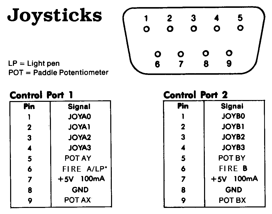
ASCII version:

 -----------------------
 \  1   2   3   4   5  /
  \                   /
   \  6   7   8   9  /
    \_______________/
  Pin| Signal      |  JS/PD |  MS:JM | MS:PM   | Note
  ---+-------------+--------+--------+---------+-----------
   1 |    JOYA0    |   up   |   up   | right b.|
   2 |    JOYA1    |  down  |  down  |    -    |
   3 |    JOYA2    |  left  |  left  |    -    |
   4 |    JOYA3    |  right |  right |    -    |
   5 |    POT AY   | paddle |    -   |  Y pos. |
   6 | BUTTON A/LP |  fire  | left b.| left b. |
   7 |     +5V     |   +5V  |   +5V  |   +5V   | max. 100mA
   8 |     GND     |   GND  |   GND  |   GND   |
   9 |   POT AX    | paddle |right b.|  X pos  |
  Pin| Signal      | Note
  ---+-------------+----------------------
   1 |    JOYB0    | up
   2 |    JOYB1    | down
   3 |    JOYB2    |
   4 |    JOYB3    |
   5 |    POT BY   | paddle potentiometer
   6 |   BUTTON B  | joystick fire button
   7 |     +5V     | max. 100mA
   8 |     GND     |
   9 |    POT BX   | paddle potentiometer
JM: joystick mode
Note: All pictures show the plug side.