MainHELP Glossary Hardware SAL Workshop Companies FTP ToolsBackAbout

Power Supply Jack (C64)

No power, no fun.


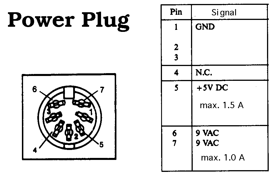
Connection scheme

Picture (ASCII version below)

ASCII version:

       _______
      /       \
     /  6   7  \
     | 3     1 |
     |  4   5  |
     \    2    /
      \_______/

Signal description

  Pin| Signal      
  ---+------------------
   1 | GND
   2 | GND         
   3 | GND
   4 | N.C.
   5 | +5V   (max. 1.5A)
   6 | 9 VAC (max. 1.0A)
   7 | 9 VAC (max. 1.0A)
Note that the voltage on pins 6 and 7 do NOT refer to ground. If you measure the voltage on either pin 6 or 7 against ground with an oscilloscope, you will get positive half-sine waves.

Note: All pictures show the jack side.


Updated: February 18th, 1998
Created: February 4th, 1997
Status : Verified on February 22nd, 1998

Site copyright © 1997 by Marc-Jano Knopp
This document is part of MJK's Commodore 64 & LCD Page
Brought back to life by Peter Schepers, Dec 10, 2005 because I really liked this site!