The Commodore C64 Diagnostic Setup
This is my personal diagnostic setup. I've had this since sometime in the mid-80's when I was an authorized Commodore repair center.
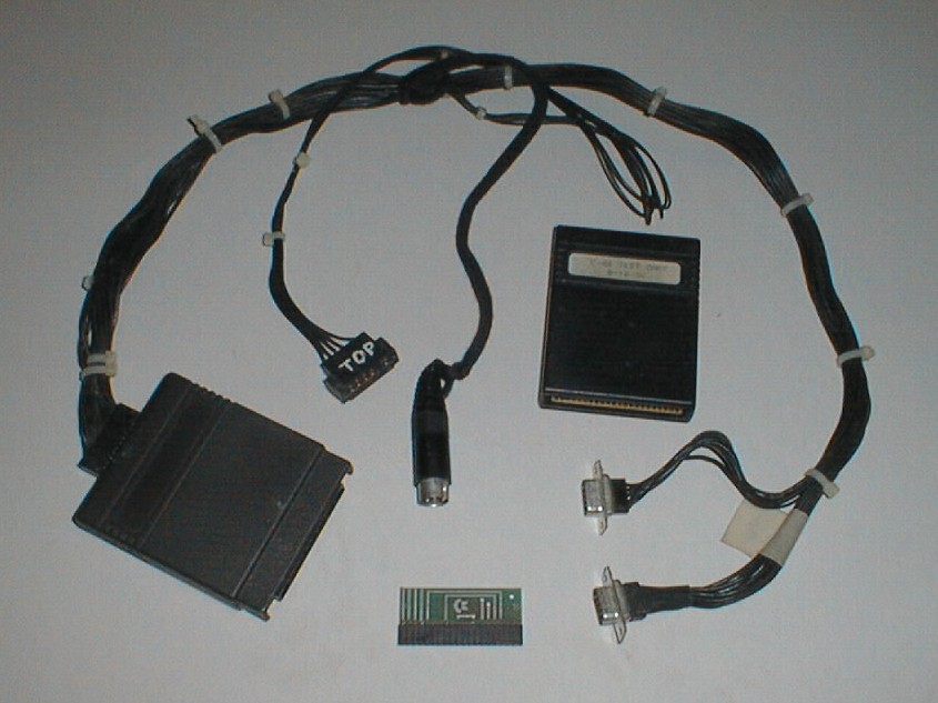 |
Figure 1 (click to enlarge) |
Figure 1 shows the cable assembly used in the diagnostic setup. The small green module in the bottom of the picture is the keyboard dongle, which is placed on the mainboard keyboard connector and simulates a key being pressed. The center serial dongle is tethered to the diagnostic cable harness with a shoelace just so I wouldn't lose it. The serial dongle is not connected to the wiring harness, and the schematic is correct.
The cartridge is the square module near the top-right with the label on it. The square cartridge on the left is the user port connector, which brings all the signals back from the various ports via the cable assembly.
The diagnostic kit is fairly good at detecting reproduceable errors. It is not good at detecting hanging and crashing problems. If you have RAM, ROM or I/O port troubles, then this will usually find it.
 |
Figure 2 (click to enlarge) |
Figure 2 shows the fully installed setup. The keyboard is unplugged internally and there is the dongle installed on the keyboard connector.
The diagnostic requires no user intervention and will red-flag suspect chips as it finds them. If you do have a hanging/crashing problem then you may or many not see any flagged chips.
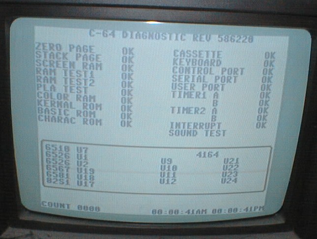 |
Figure 3 (click to enlarge) |
Figure 3 shows the diagnostic running, at the end of one pass #1. It is in the middle of the sound test right now, just about to start pass #2. Because the diagnostic will run forever, it is good for catching flaky RAM.
Without the keyboard dongle installed, the keyboard entry will show up as bad, and likely 6526 U1 will be flagged as well.
The Sound Test is handly for catching slightly flawed SID chips, something which was not uncommon. A series of waveforms are played (sawtooth, sine, triangle and noise) over different voices. If one voice is missing or distorted, you know to change the chip. This condition will not flag the chip as bad.
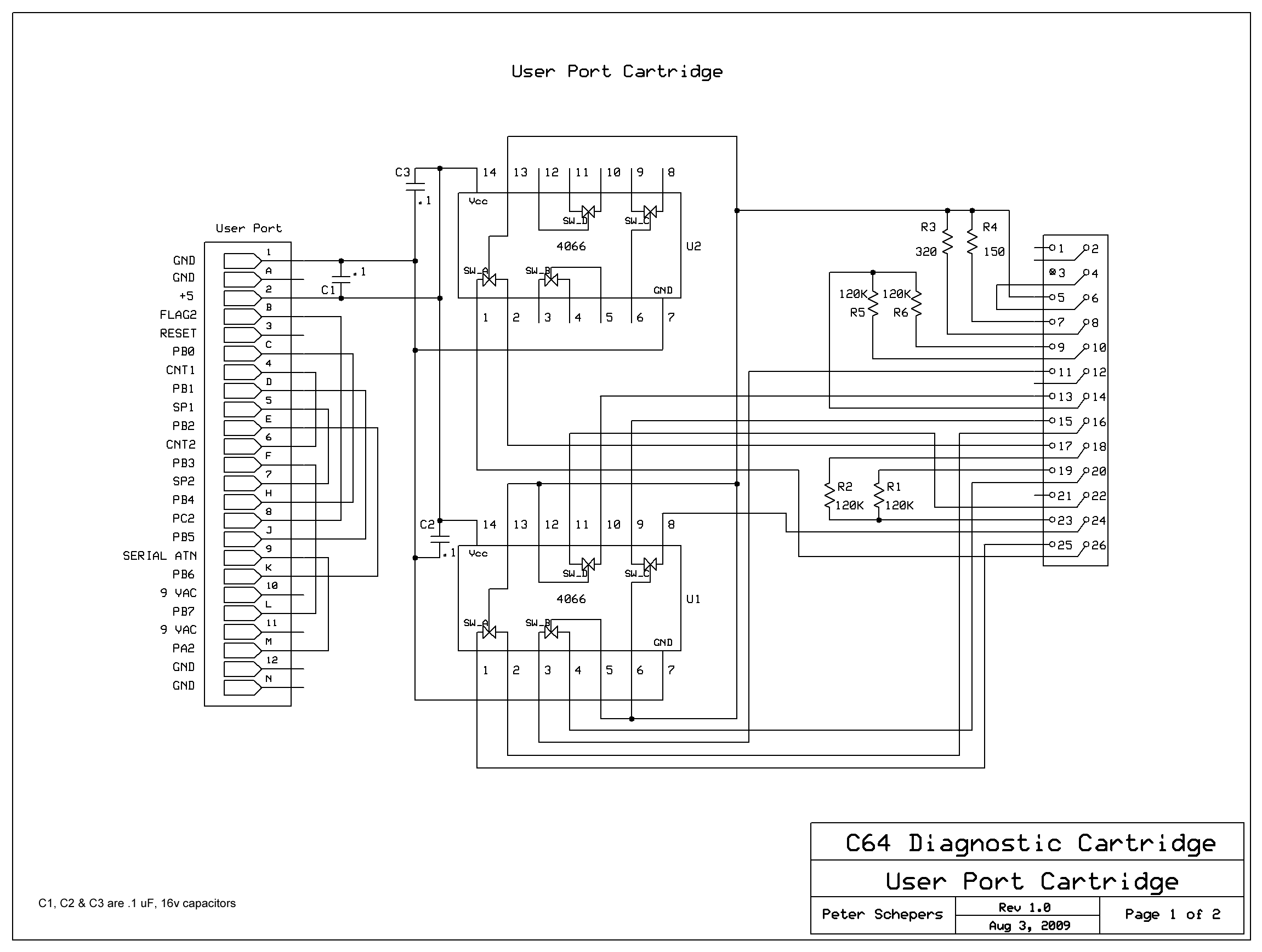
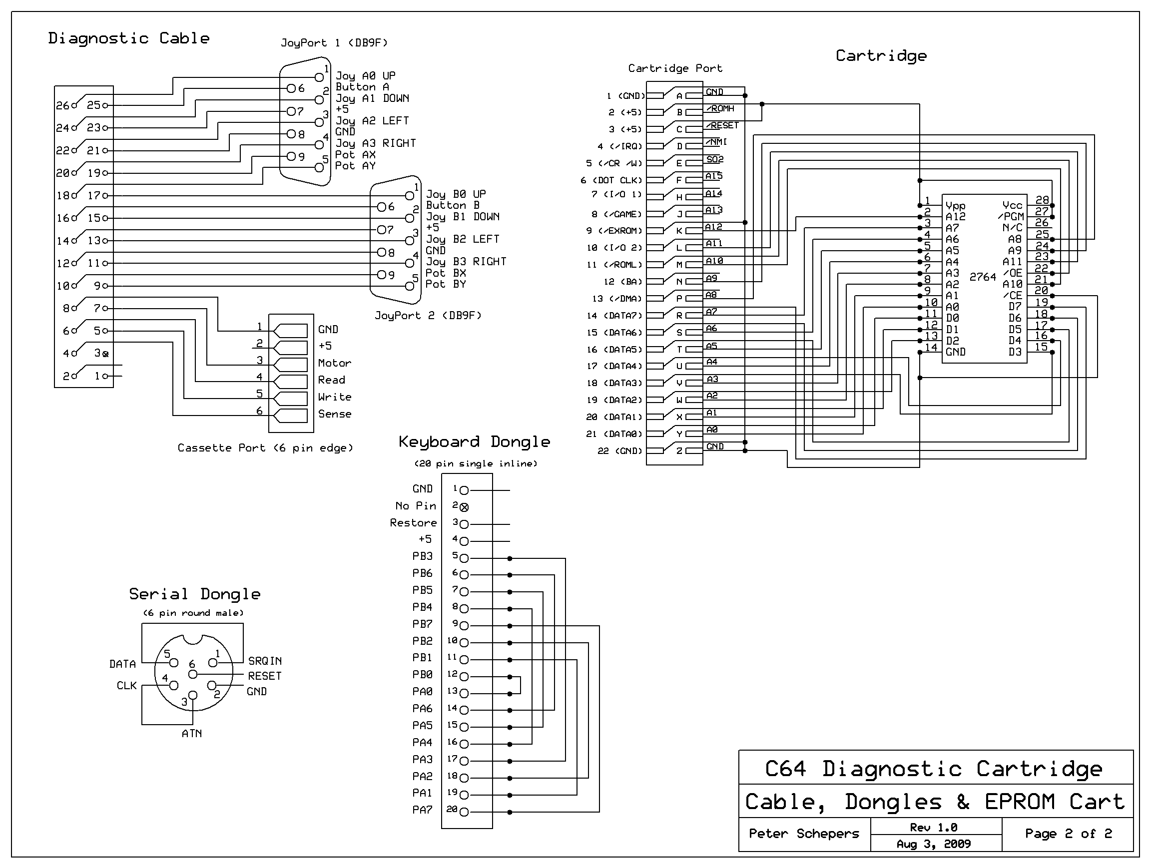
Diagnostic Schematics
The schematics below show the construction of my diagnostic jig including all the dongles, the cable harness and both the user port and EPROM cartridge. Page 1 is the user port cartridge, and page 2 is all the rest.
 |
 |
Click here to download the ROM image used in the above diagnostic cartridge.
Building the keyboard diagnostic header
This section details how to build the keyboard diagnost attachment. This is normally a single inline 20 pin header, but using a piece of an old 40-pin IDE ribbon cable is good recycling and it fits perfectly.
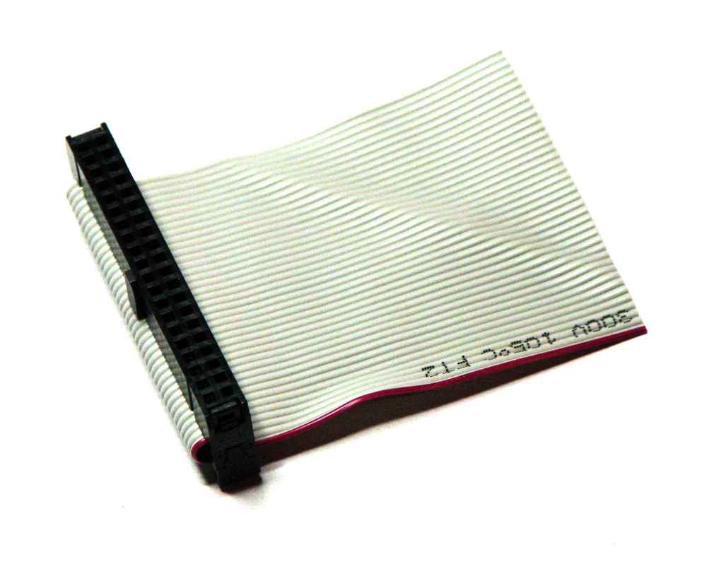 |
Step 1: Obtain an old 40-wire IDE ribbon cable with the 40-pin connectors attached. Cut the cable about 2" (5 cm) from the end of the cable/connector. This is a good connector because it fits the keyboard plug and you have two rows to work with. The newer 80-wire cables will not work. |
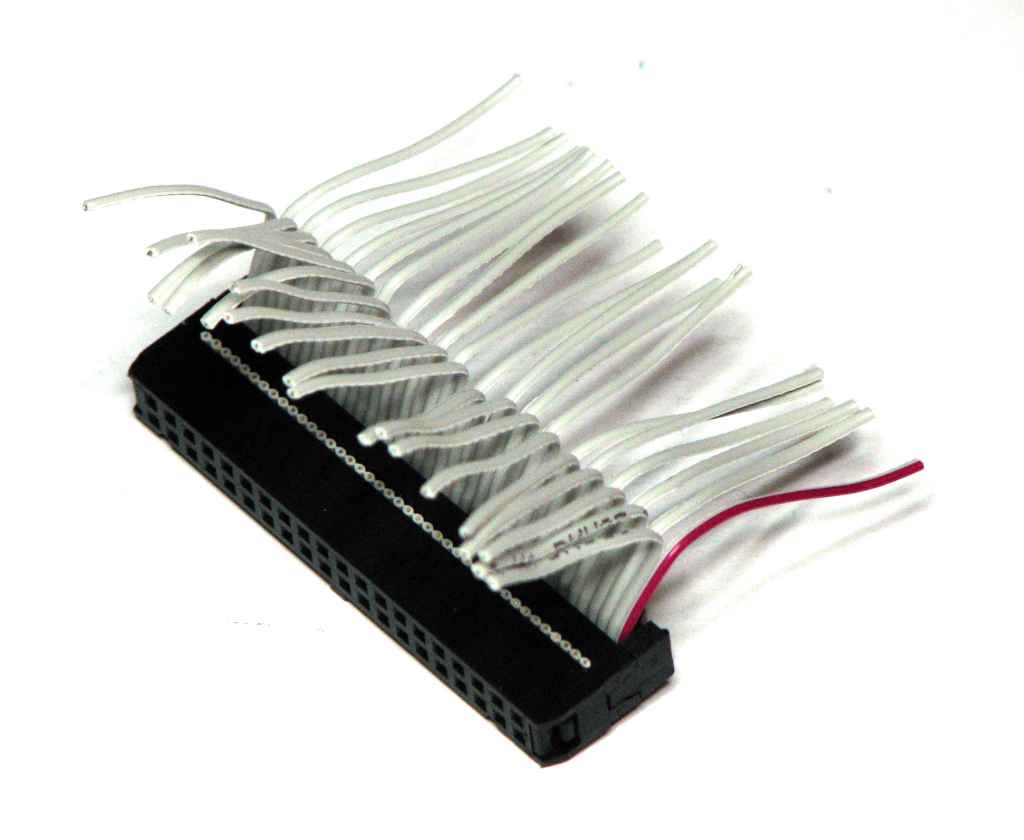 |
Step 2: Split the wires back about 1.5" (4 cm). Separate the wires so all odd wires point one way (starting with the marked pin1 wire), and the even wires point the other way. Wires numbering is now from 1 to 20, on both sides. |
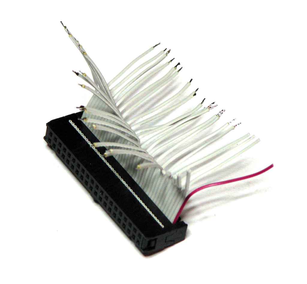 |
Step 3: Strip wires 5-20, on both sides, back about 1/8' (3mm). Twist & tin the wires. Leave wires 1-4 on both sides as they are not used and will be removed later. |
 |
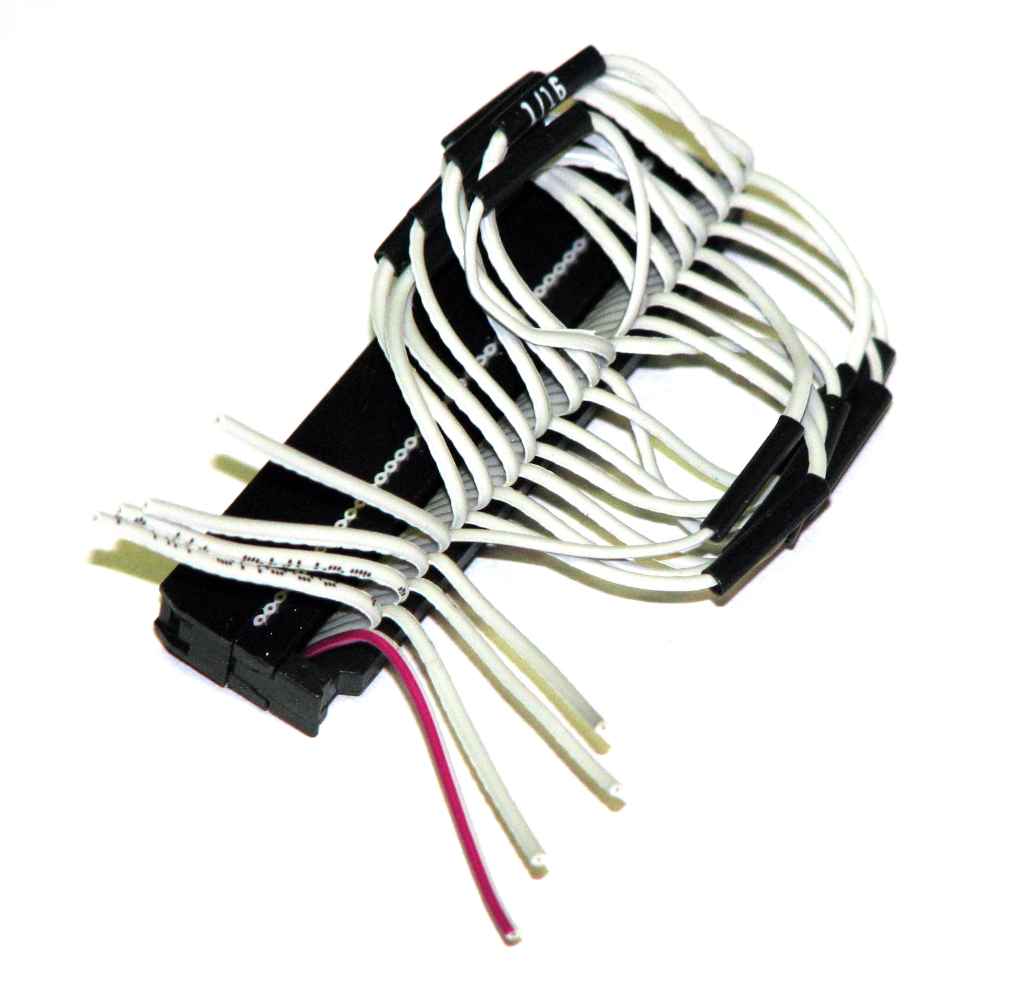
Step 4: Solder wire pairs together, on both sides, using the following chart. Use 1/16" heat shrink to cover each solder joint.
Cut off wires 1-4 from both sides & shrink the heat shrink tubing to complete the cable. |
 |
The completed cable. |
Email the author: Peter Schepers | Last updated: Sept 12, 2011