Ports, part descriptions and pinouts
Below are the common ports and parts used to make the various cables.
 |
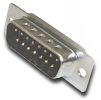 |
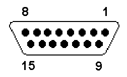
This is a diagram of a DB15 connector. It is used for the parallel port add-on on the C= 1541 and 1571 disk drives. It is shown from the solder cup side. Below is a pinout of the port as installed in the drive:
|
||||||||||||||||||||||||||||||||||||||||||||||||||
|
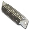 |
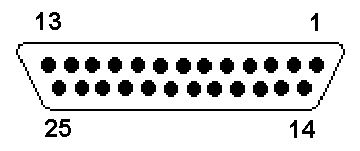
This is a diagram of a DB25 connector. It is used to connect the X cables to the PC's parallel port. It is shown from the solder cup side. Below is a pinout of the PC parallel port:
|
||||||||||||||||||||||||||||||||||||||||||||||||||
 |
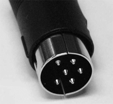 |
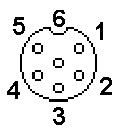
The DIN6 round connector is found the C= serial disk drives, such as the 1541 and 1541. The pinout on the left is taken from the back (solder side) of the connector. Below is a pinout of the C= drive serial port:
|
||||||||||||||||||||||||||||||||||||||||||||||||||
 |
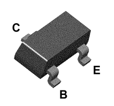 |
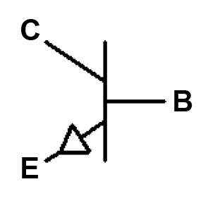
This is the diagram and a picture of the BSV52 surface mount NPN transistor. The XA and XAP cables use this transistor type. This is a very tiny component, thus working with them is hard! | ||||||||||||||||||||||||||||||||||||||||||||||||||
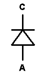 |
This is a diagram of a general purpose diode. The XH/XXH use 1N4148 diodes (general purpose) but the XE/XEP/XM/XMP use 1N5819 Schottky diodes. These diodes only allows current flow from the anode (A) to the cathode (C) and prevent it in the opposite direction. | |||||||||||||||||||||||||||||||||||||||||||||||||||
 |
This is a diagram of the resistor, and they limit current flow in a circuit. These are only used in the XA/XAP cables, to limit current flow and setup proper voltage biasing for the transistor. |
Email the author: Peter Schepers | Last updated: Mar 17, 2009