Installing the 1541 Parallel Port Option
Parts needed:
Drill, bits and files to make & shape the hole in the 1541 chassis.
Introduction
This cable hooks up to one of the 6522 VIA IC's. The chip location varies depending on which model of 1541 drive you have. The easy way to tell which chip to use is to look for the VIA chip which has no traces attached from pin 2 to 9 (or only one to pin 2).
- On the 1541 long board the chip number is UAB1. The board in this drive is the full length of the chassis.
- On the 1541 short board the chip number is UC3. This board in this drive is about 60% the length of the chassis.
- On the 1541C the chip number is UC1. This board is very short, about half the length of the chassis.
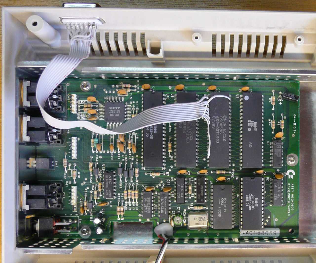
- On the 1541-II the chip number is U6.
There is no guarantee that the 6522 chip will be socketed but it typically is in most 1541 (long and short board) and 1541C models. The 1541-II does not have the 6522 socketed and requires a soldered cable. If the 6522 is socketed then pop out the chip, insert the wired machine socket, and re-insert the VIA into the new socket. .If the VIA is not socketed, you can either install a socket for the VIA chip or go for the soldered cable and solder the parallel port wires directly to the VIA chip (top or bottom of the board).
On the 1541C and the 1541-II, the trace to pin 2 on the VIA will need to be cut. The 1541C also needs the 251968-01 (or 251968-02) ROM at position UA2 changed with one from a 1541-II (251968-03). The original 1541 ROMS will not work as they used two ROM IC's, the 1541-II and 1541C use a single combined ROM.
Step 1: Build the internal parallel cable
Click here for the instructions on how to build the internal parallel cable for your 1541 drive.
Step 2a: 1541 & 1541C chassis modifications
If you have a 1541-II, see step 2b.
Installing a parallel port in a 1541 & 1541C is not too hard as the outer chassis is the same between the two models, and there are many ways to go about it. One is to put the port out the back, above the power switch. The other is to go out either side of the drive. You could even go out the bottom chassis so removal of the top won't be hindered. Regardless of where it is installed, it is best if the connector is installed with pins 1-8 at the top.
The Rear Install
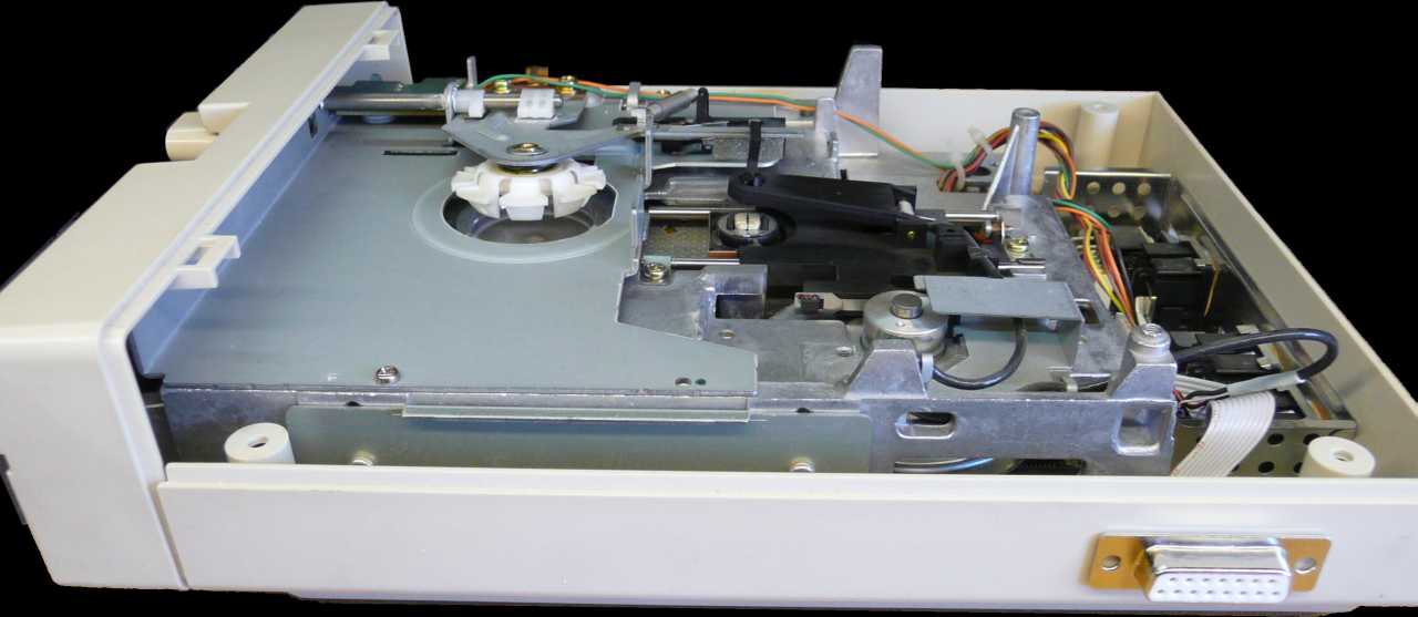
For the rear installation, the connector must be installed on the outside of the case in order for it to fit in the back. Don't put the connector too far down or one of the rectifiers on the main board gets in the way. Don't put it over too far to the left as the mount post for the bottom case screws is there. The connector edge should be about .5" from the top of the drive, and about 3/4" from the left. To make the hole for the connector, drill a few 1/4" pilot holes where the connector is to go, and file the hole down until the back side of the connector fits snugly and flat against the outside of the case. Mark the bolt holes with marker and drill the holes for the hex bolts. Solder the ribbon cable to the DB15 connector, and this cable will connect to the VIA in the drive. Feed the cable through the hole in the chassis and bolt/nut the connector in place. Hex bolts and nuts from old PC parallel and serial ports should be used to secure the connector to the case. These also allow the external parallel cable to be screwed to the connector so it won't fall off during usage. The first picture below shows the inside of the chassis, with the cable connected. The ribbon cable is about 12" long which is more than enough length when the top case needs to be removed. The second picture shows the completed port out the rear.
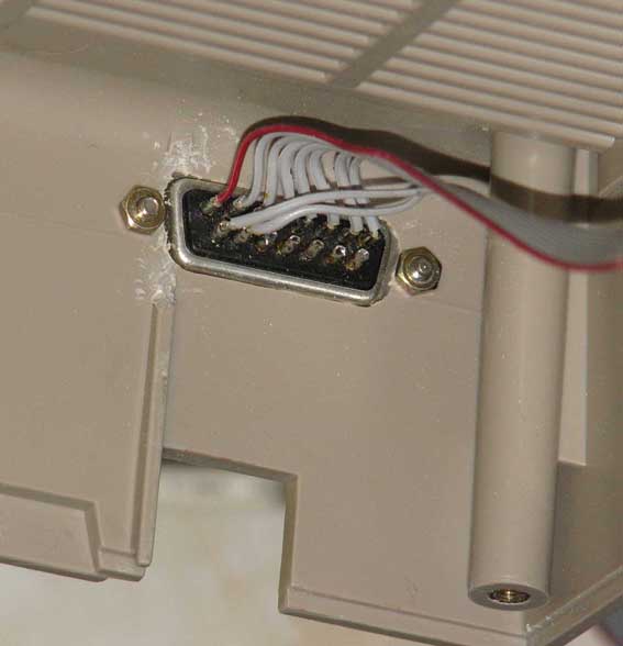 |
Inside the chassis. Some plastics need to be removed to fit the screws. |
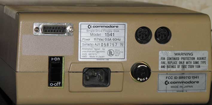 |
The rear of the chassis. While the color of the 1541C is slightly different, the chassis is the same as a normal 1541. |
The Side Install
This is not the preferred method because the parallel cable will get in the way sticking out the side. If this is still preferential, it is your choice as to which side it best as it all depends on where the drive is located and what's near it. Either side inside the 1541 provides enough room, just put the connector no higher than 1/4" from the top. Choose your side, mark off the connector location with a pencil outline, and drill some 1/4" pilot holes. File down the opening until the DB15 connector fits snug from the outside of the case. With the connector in the hole, mark off the bolt holes and drill them. Solder the ribbon cable to the DB15 connector, fit the cable through the hole from the outside and bolt it in place. The picture below shows a users installation out the left side, including reset and device selection switches.
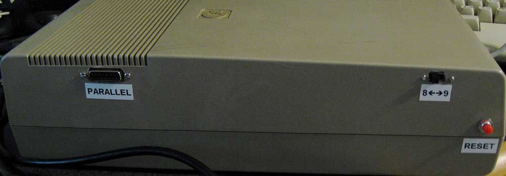 |
The side install |
Step 2b: 1541-II chassis modifications
 |
This is the rear port install. It's a good location because the cable goes out the same location as all the others. The only problem with installing the port in the top case is it cannot be moved out of the way whenever you open the drive. |
 |
This is the side port install. This location requires much room on the side to hook up the parallel portion of the X cable, but it leaves the top case free to be removed. The choice is yours. |
Step 3: 1541C and 1541-II required board modifications
1541C changes
The 1541C requires some extra changes to the board before adding the socket or soldering the ribbon cable wires to the board.
- You will need the 1541-II ROM (version 251968-03) to replace the existing 251968-01 or 251968-02 ROM at position UA2. The 1541-II firmware doesn't use the optical sensor present on the 1541C mechanism (and wired to UC1 6522 pin 2, PA0). The ROM is well labeled, so it is easy to find and is usually socketed for easy removal. The good news is a 27128 EPROM is pin compatible with these ROM's, so you can burn one from the above binary file, or you can purchase one of these burned EPROM's from my cables page.
- You will need to cut a trace to disconnect the optical sensor from UC1. See the second picture below which shows what trace to cut and where circled in red and pointed at with an arrow. Without cutting the trace, the parallel port simply will not function. (If you are using a socketed parallel cable, you can instead cut off pin 2 from the adapter cable 40-pin socket and file it down so it won't touch the VIA socket on the 1541C when inserted.)
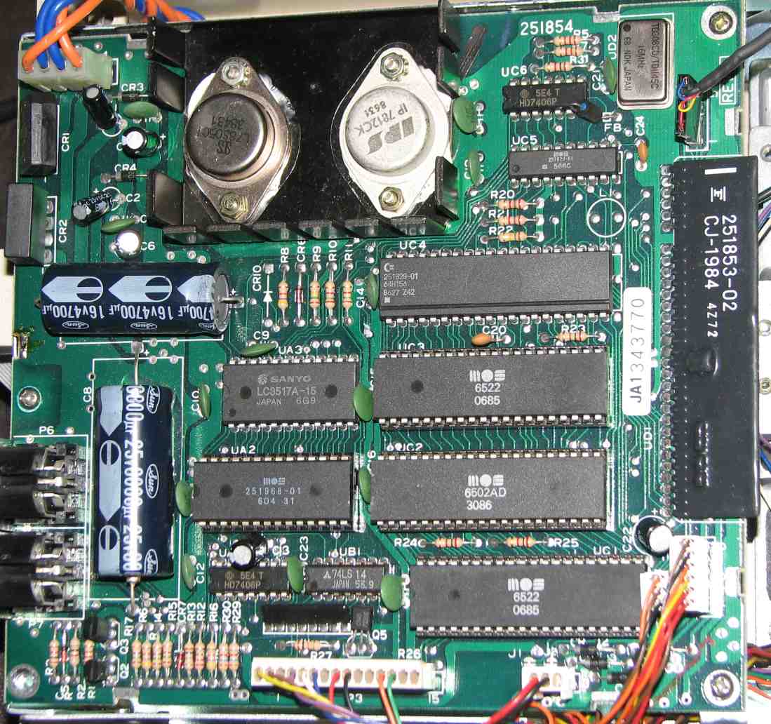 |
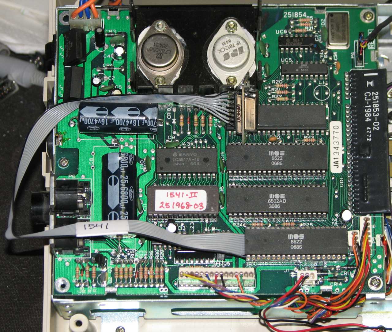
The 1541C board, rev 251854. |
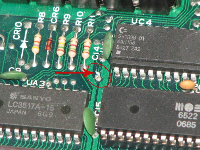 |
The arrow points to the location of the already-cut trace. This seemed like the simplest location to cut the trace. Most of this trace is on the top of the board, and not having to remove the board is simpler. Probably the best approach would be to install jumper pins where the trace is cut so that with the insertion of the jumper and the replacement of the original 1541C ROM, you would have the drive back to factory operation. |
1541-II changes
The 1541-II must have a trace cut on the bottom of the board which connects pin 2 to pin 1 on the 6522 VIA. Without this pin cut, the parallel port will not work. Removal of the board is not difficult, with only four screws to remove the top cover, four screws for the drive assembly and three for the board. I recommend marking the drive mechanism connectors on both the connector and the board with numbers so you don't get their re-installation wrong.
(If you are using a socketed parallel cable, you can instead cut off pin 2 from the adapter cable 40-pin asocket and file it down so it won't touch the VIA socket on the 1541-II when inserted.)
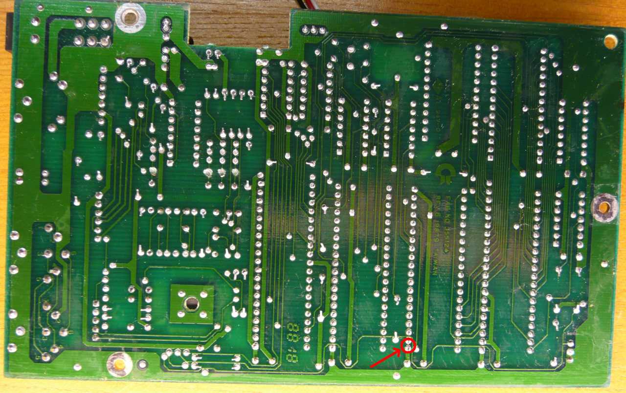 |
The bottom of the 1541-II logic board. The red arrow in the picture points to the location of the cut trace. |
Step 4a: Solder the ribbon cable to the VIA chip (6522 chip soldered in)
If the VIA chip you need to connect to is socketed, and you have or want to use the solderless socket solution, go to step 4b.
There are two different 1541's models that I have worked with, the long board and the short board. There are also two different ways to solder the parallel cable to the VIA chip, to the top of the IC or to the socket solder pads on the bottom of the board. The installation for both types of boards and both cable approaches is documented below. Follow the chart below to connect the wires, and be sure to use ESD procedures (electrostatic discharge) when working on the main board.
1541 Short board soldered install
In this short board install, the ribbon cable is soldered to the top of the socketed 6522 VIA chip located at UC3. This was my first install, and soldering to the top of the chip was easier as the board didn't have to be removed. However it is not a very clean method as the chip now has solder on many of the legs, the parallel cable gets in the way, and removing the 6522 for testing also removes the parallel port.
 |
The short board install, with cable soldered to the top of the VIA chip. |
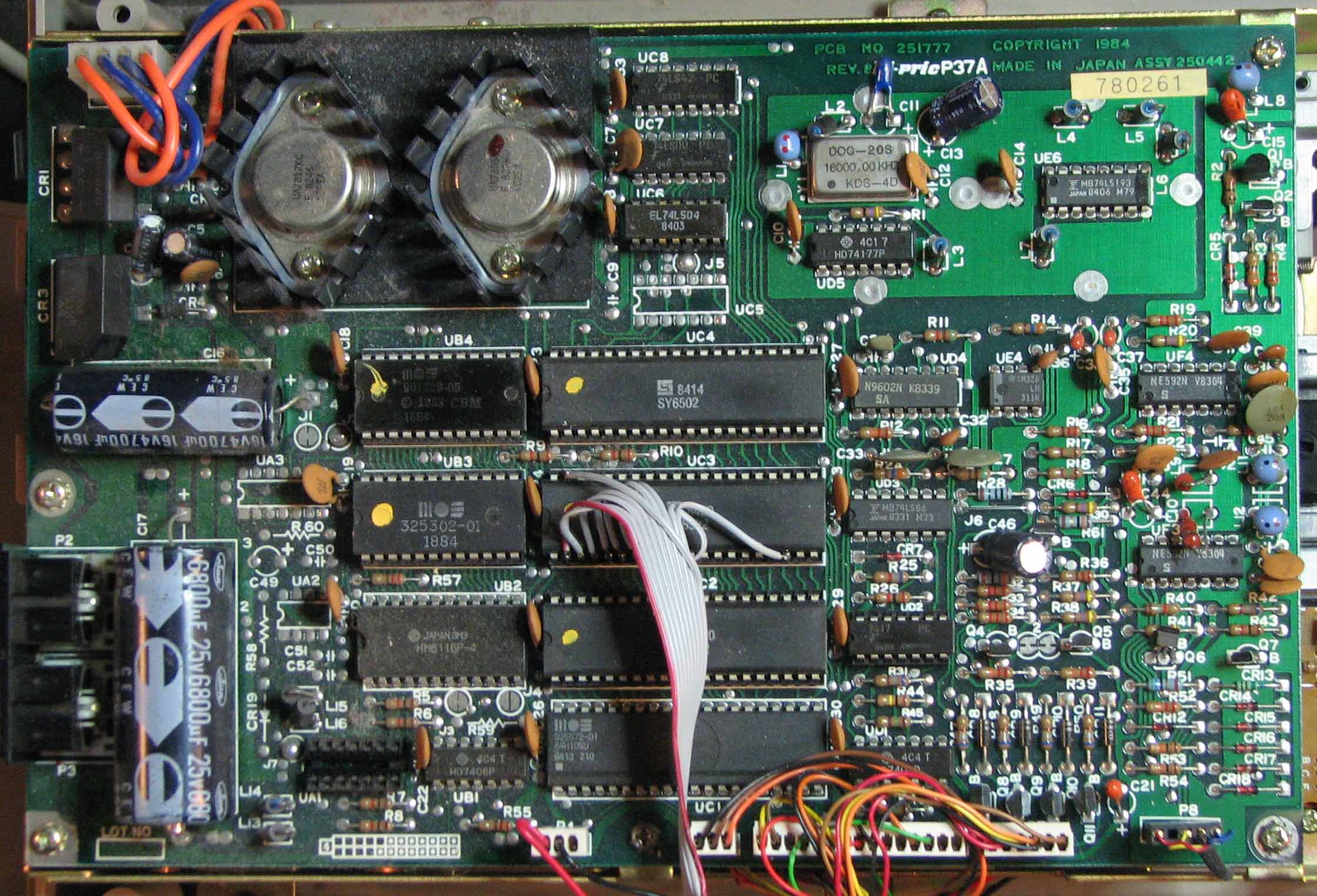
1541 Long board soldered install
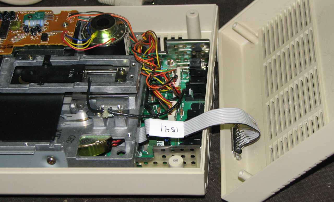
The long board installation, with the parallel cable soldered to the bottom of the board, is show below. In the second picture, the ribbon cable is soldered to the bottom of the board to the 6522 VIA chip located at UAB1. This was my later installation and even though it meant removing the board to install the cable, it looks much neater, the VIA chip can be removed if needed, and the parallel cable is out of the way. Later, I built the solderless socket cables which I now use exclusively.
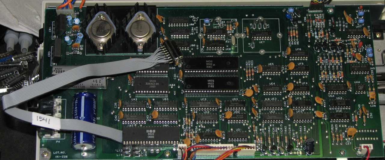
 |
The 1541 long board |
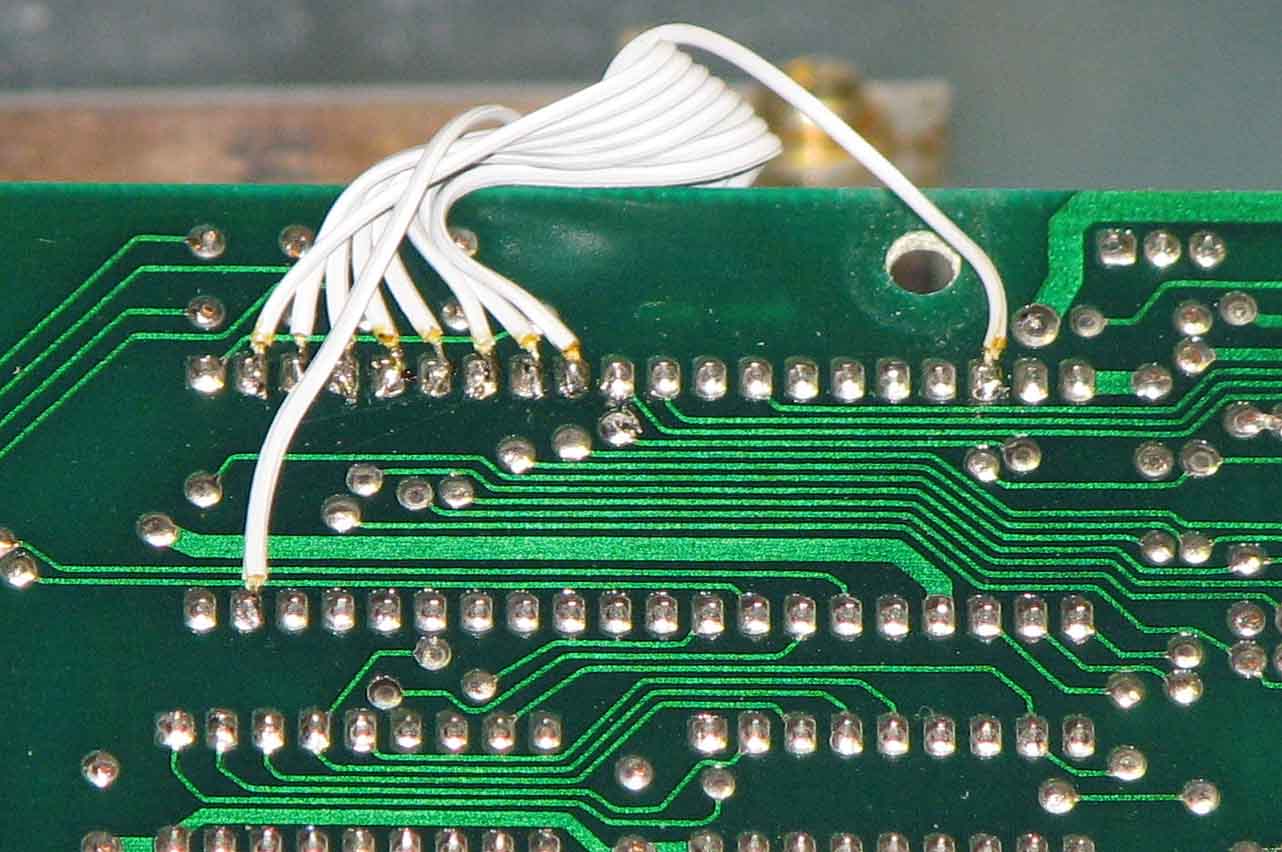
|
Cable installed on the underside of the board. |
1541-II soldered install
 |
The soldered cable installation, going out the side. This is the easiest method for the 1541-II as the 6522 chip is usually soldered. While the solderless socket solution will work, it does mean removing the board, desoldering the 6522, and installing a socket. This is not recommended unless you have good experience desoldering chips. |
1541C install
Since the 6522 appears to be socketed in this model, I didn't bother to install a soldered port, but rather installed the socketed solution. If you wish to install a soldered port, the instructions are similar enough to the 1541 short-board install, just remember that the chip is at location UC1.
Step 4b: Insert the parallel VIA socket cable (6522 chip in socket)
First, feed the parallel socket/cable through the newly-created hole in the chassis, socket first and bolt it to the chassis. Find the proper socketed VIA chip and remove it (see the location at the top of this page). Insert the precision socket into the VIA socket, matching pin 1 on the sockets. Once installed, re-insert the VIA chip into the precision socket, matching pin 1 again.
1541 Short board install
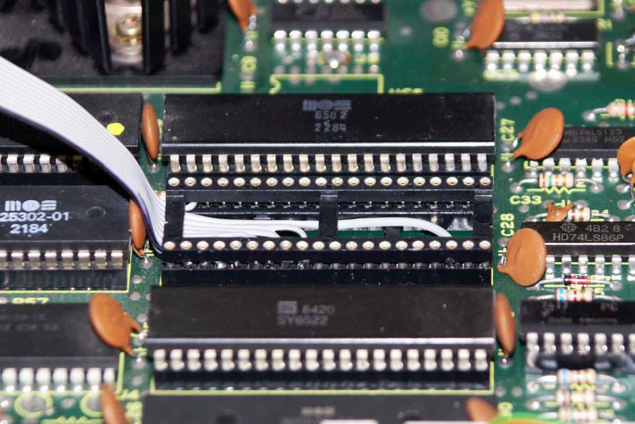 |
Solderless socket installed |
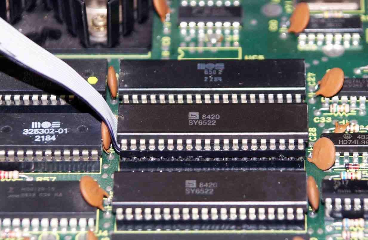 |
VIA re-installed |
 |
The overall height of the solderless socket solution. The tallest chip of the three is the parallel cable. The front chip (lowest) has no socket, the middle is socketed. The double-socket will raise the height of the chip up a bit, but there's lots of room in this model. |
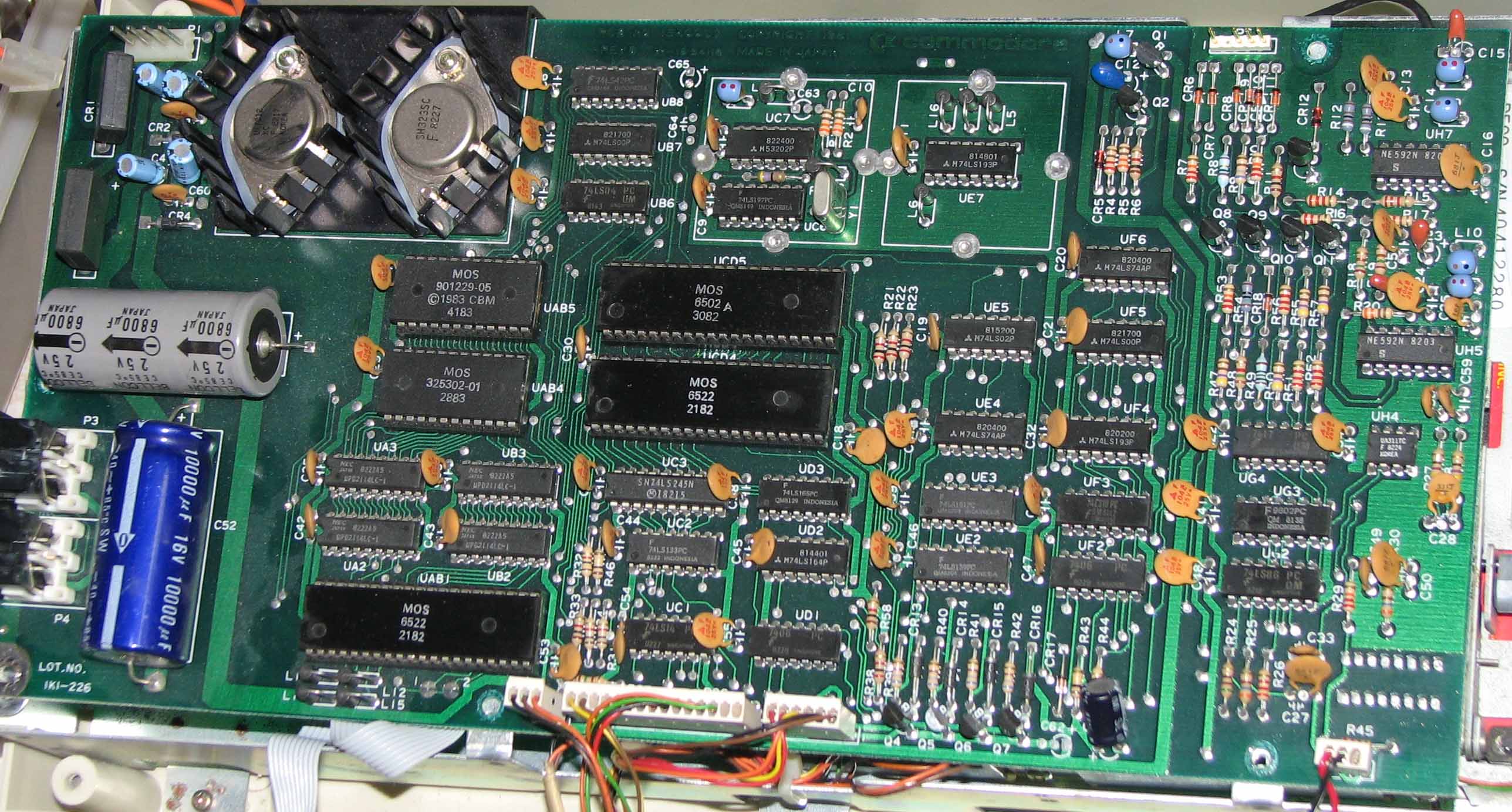
1541 Long board install
 |
This is the long board with the solderless parallel cable installed. |
1541-II install
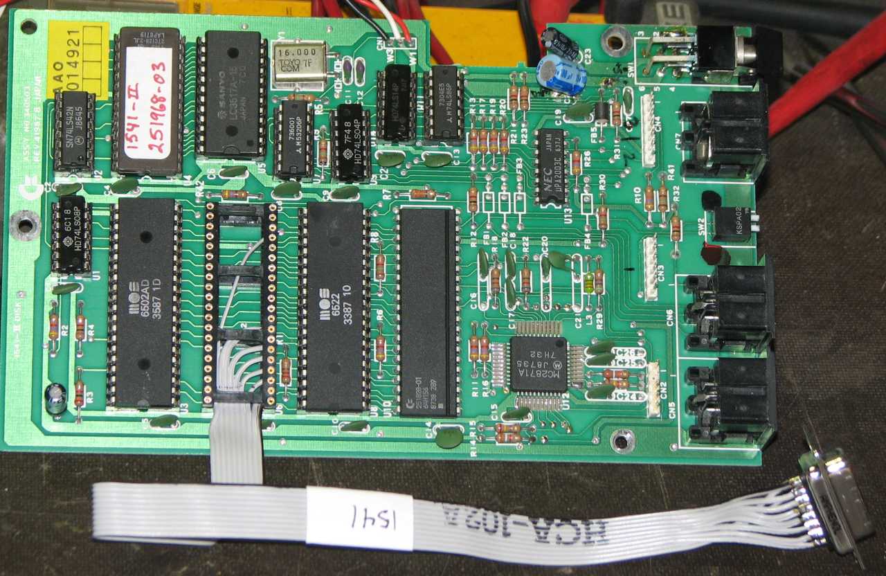 |
VIA chip removed and the socket installed. Even though this chip is not normally socketed, I had to make repairs to the board and so installed a socket for many of the chips. |
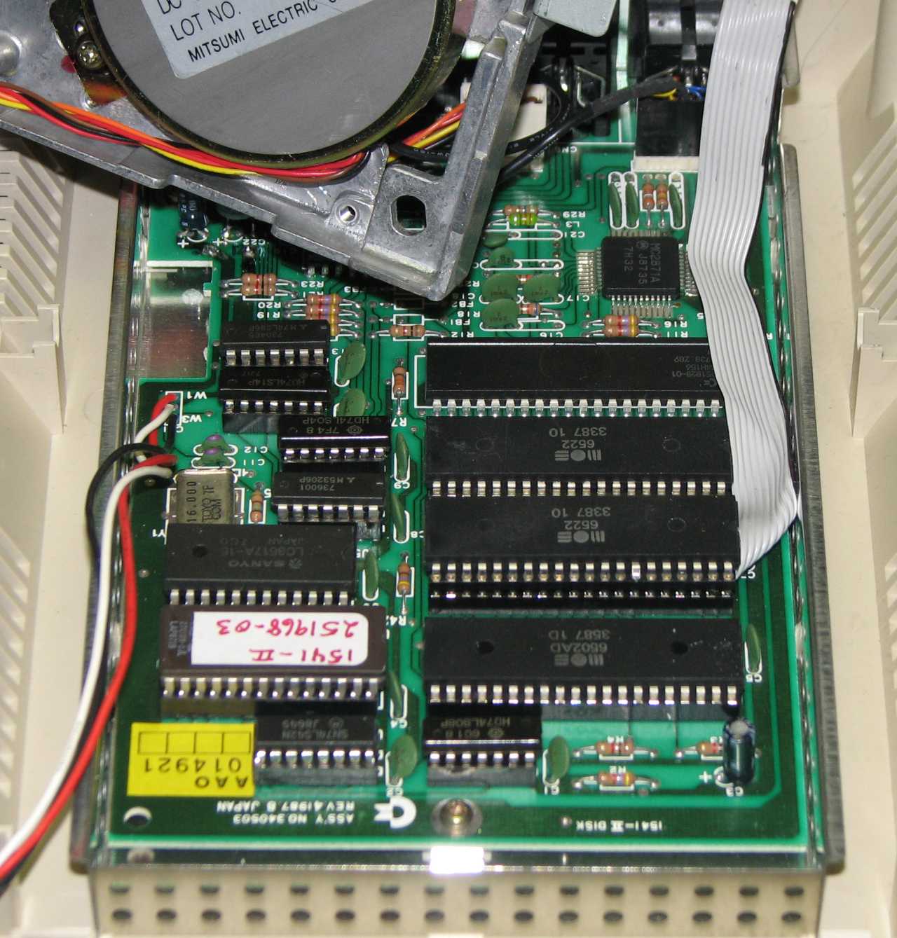 |
The board is back in the drive, the VIA chip is re-installed, and the ribbon cable is routed to the back. YES, there is enough room between the stepper motor and the 6522 when it is socketed, about 3/16" (3 mm), for the socketed solution to work. I've read several times that the socketed solution won't work because there's not enough vertical space, but I've proved it works quite nicely. |
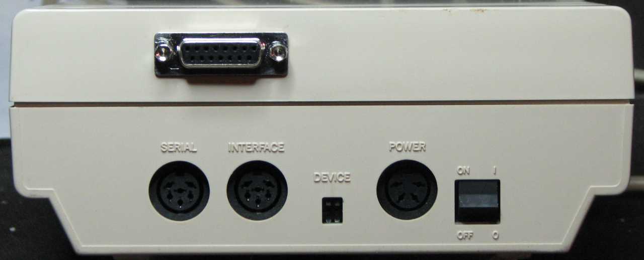 |
The completed 1541-II rear installation. |
1541C install
 |
The 1541C cable, with the solderless socket installed. Once again, the double-socket will raise the height of the chip up a bit, but there's lots of room in this model. |
Pinouts for DB15 to 6522 VIA
DB15 |
VIA#1 |
1 |
2 (PA0) |
2 |
3 (PA1) |
3 |
4 (PA2) |
4 |
5 (PA3) |
5 |
6 (PA4) |
6 |
7 (PA5) |
7 |
8 (PA6) |
8 |
9 (PA7) |
9 |
18 (CB1) |
10 |
39 (CA2) |
Email the author: Peter Schepers | Last updated: Feb 15, 2010