Building the 1571 Internal Parallel Cable
Parts needed: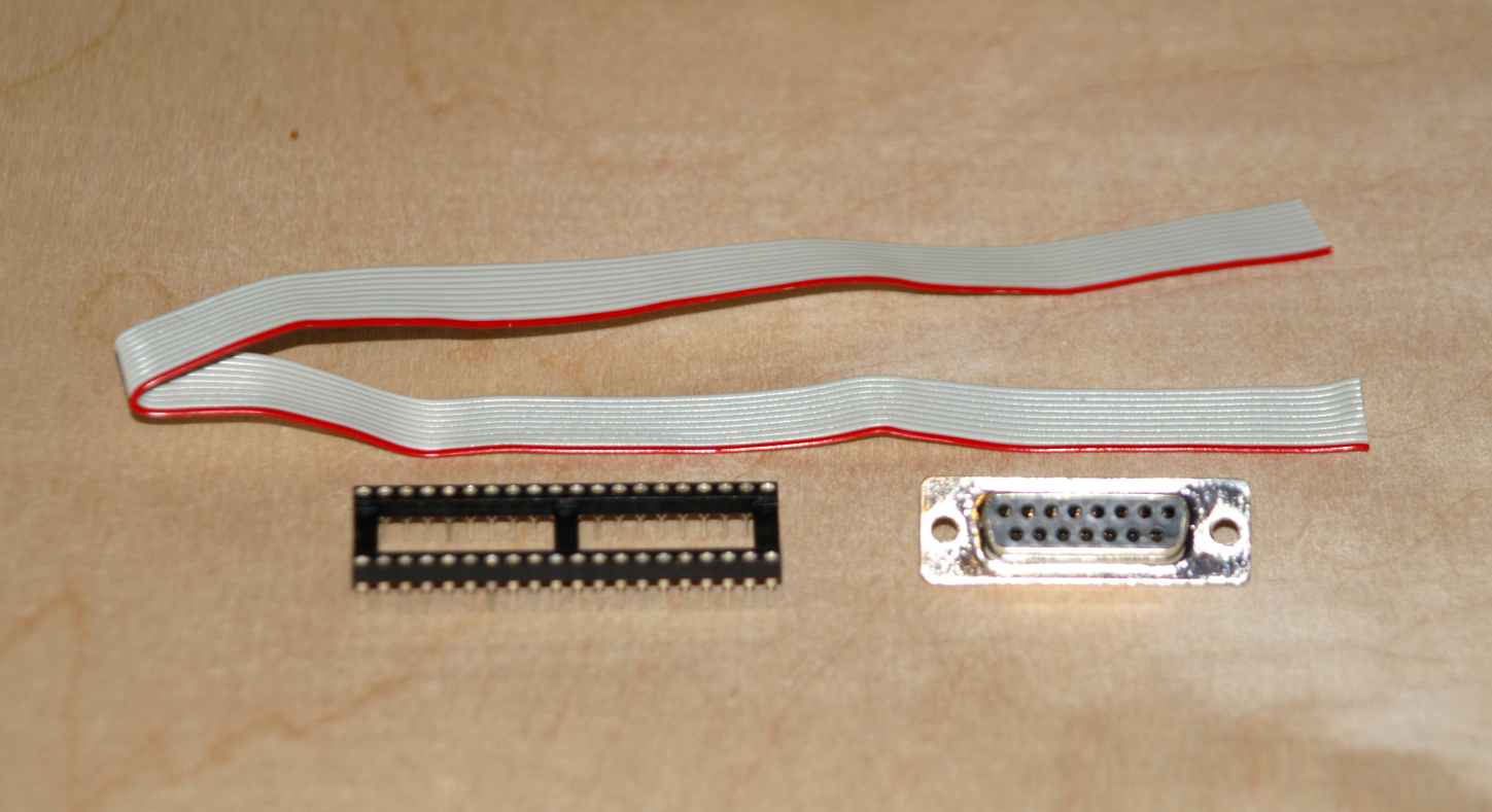
12" of 10-conductor ribbon cable, with wire 1 marked in a different color
1 DB15 female connector
1 40-pin low profile precision socket (optional, for the socketed cable)
Getting started
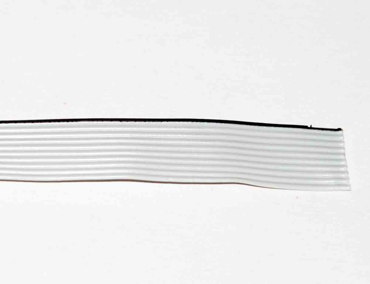 |
Step 1: Get some ribbon cable Get about 12" of 10-wire ribbon cable. If wire 1 is not marked in a different color, choose your wire 1 and color it with a marker. A section of an old 40-pin IDE cable works well. The example here has wire 1 colored with a black marker. |
 |
Step 2: Prepare one end We need to solder one end of the ribbon cable to the DB15 female port. Using fine scissors cut the wires apart back about 1" (3cm). Be sure not to cut to close to the wires while separating the wires to expose or cut them and cause shorts. Strip the wires back about 1/8" (3 mm) and twist and tin the wires. |
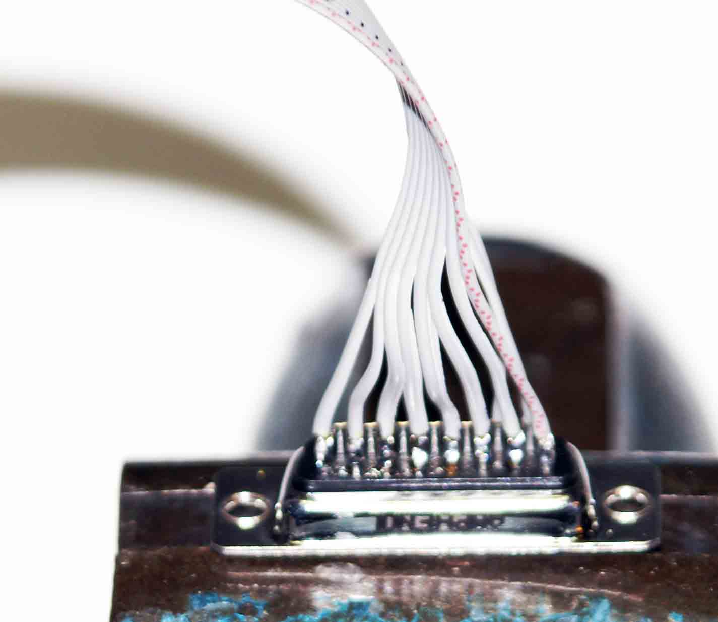 |
Step 3: Attach wires to DB15 port Pre-solder the DB15 solder cups pins 1 to 10 so wire insertion will be easier. Starting with wire 1 on the ribbon cable, solder wire 1 to pin 1 on the socket, wire 2 to pin 2, etc. Wire 9 and 10 will go behind the front set on the second row. |
Step 4 is for the simpler soldered cable. For the socketed cable, follow steps 5a-5d.
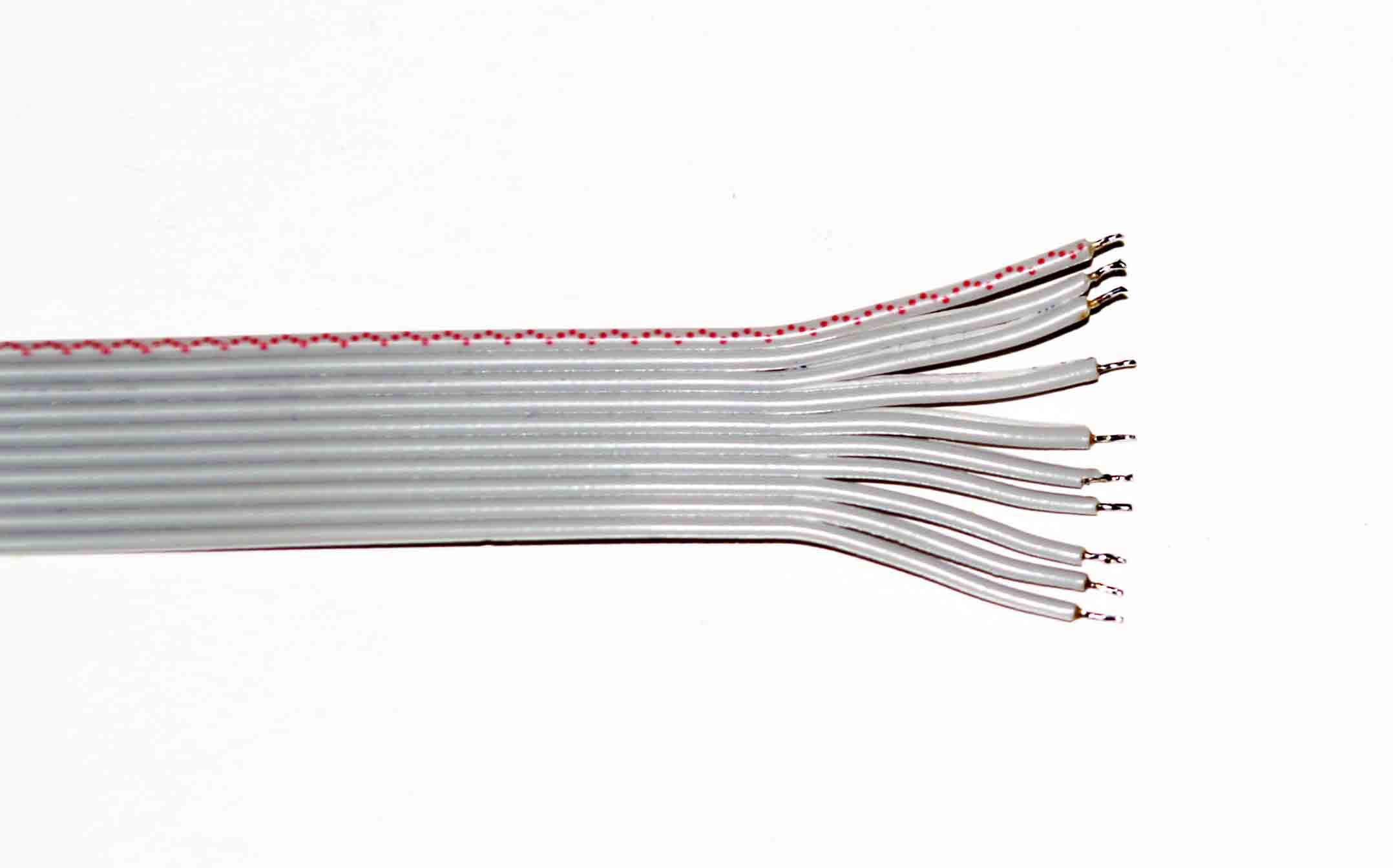 |
Step 4: Prepare other end Just like the one end that was stripped and soldered to the DB15 connector, we need to prepare the other end of the ribbon cable for soldering to the chip legs. Using fine scissors cut the wires apart back about 1" (3cm). Be sure not to cut to close to the wires while separating the wires to expose or cut them and cause shorts. Strip the wires back about 1/8" (3 mm) and twist and tin the wires. Wires 9 and 10 can be separated from the main group by about an extra .5" (1cm). |
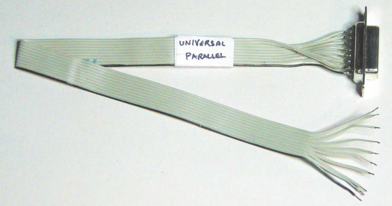 |
The finished soldered cable This is the finished cable. Label it "universal" because it will fit both the 1541 and 1571. |
Steps 5a-5d are for the socketed cable.
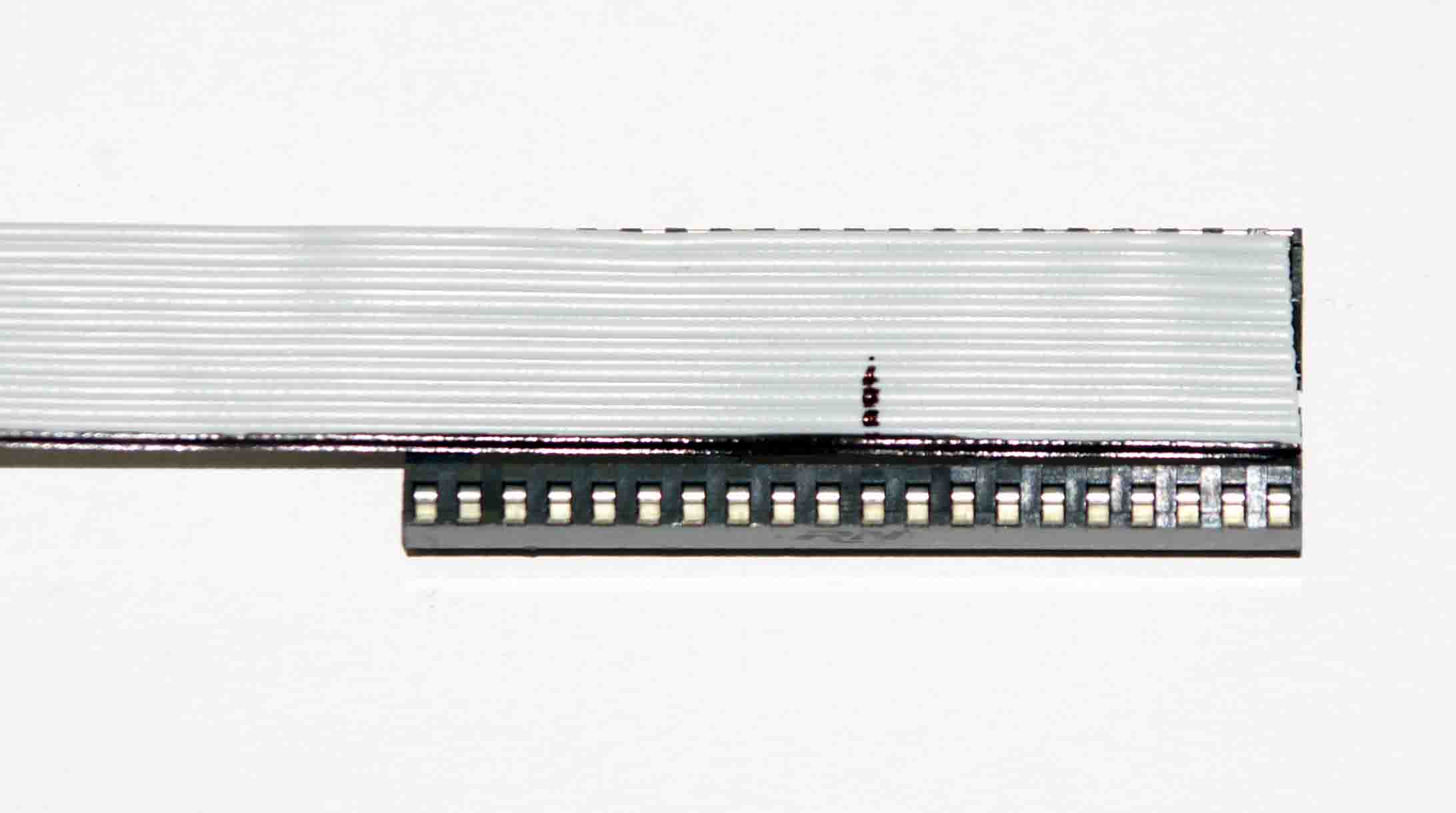 |
Step 5a: Mark off the starting pin Get a 40-pin socket and lay the cable on the socket with wire 1 towards you so the right end of the cable is flush with right end of the socket. With a thin marker or pen, mark the cable at socket pin 11 (1 is on the left of the socket, 20 is on the right). |
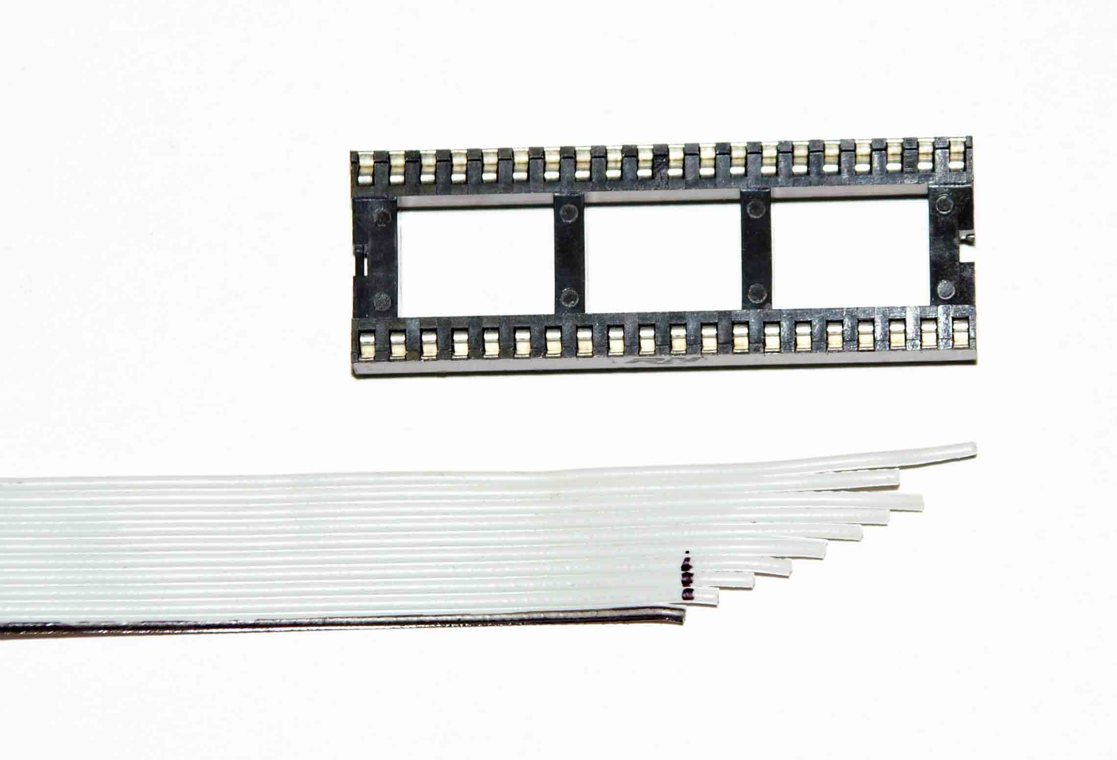 |
Step 5b: Trim the wires Starting from wire 1, cut wire 1 at the mark you just made, cut wire 2 about 3 mm to the right, cut wire 3 about 3 mm further to the right etc until you get to wire 8. Wire 9 will be cut to the length of wire 7, and wire 10 will be left at its full length. This should leave you with the wire trimmed as seen. |
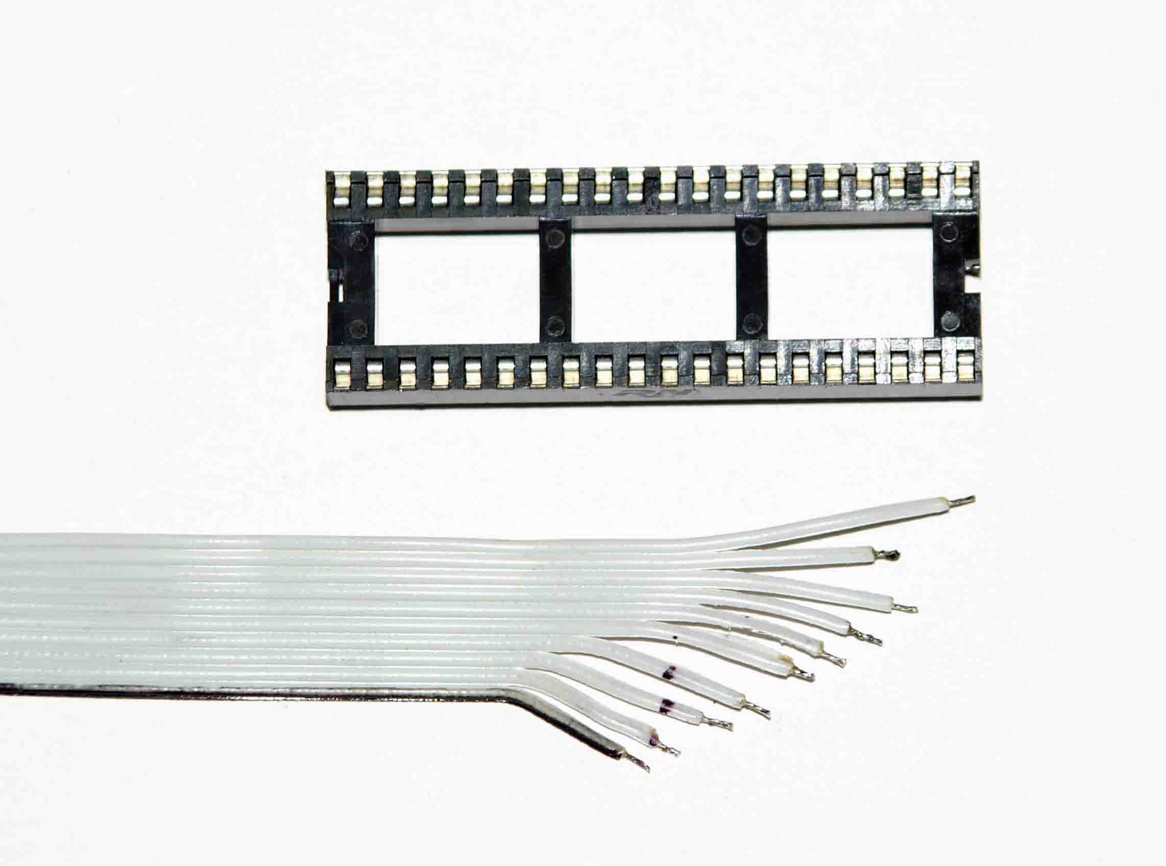 |
Step 5c: Strip and solder wires Using fine scissors, cut the wires apart back about 1". Be sure not to cut the wires or get too close as you will expose the inside wires, possibly causing shorts. Get your wire strippers and strip the wires back only about 2 mm (about 1/8"), not too long. Twist and tin the wires. |
 |
Step 5d: Attach to the socket Turn the ribbon cable over so wire 1 is away from you. Turn the socket over so the pins are sticking up and pin 1 is at the top-left corner (pin 1 is on the side where the notch is cut in the side of the socket body). Solder the wires to the socket pins (right next to the socket body) using the chart below. It might be handy to pre-solder the necessary socket pins first. |
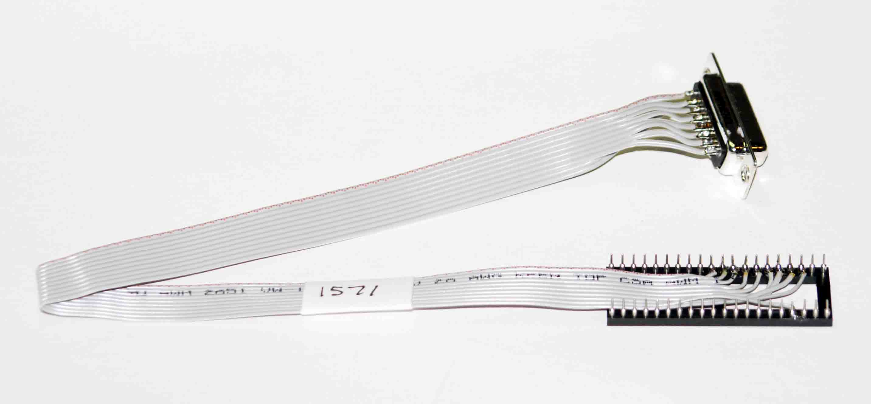 |
The finished cable This is the finished cable. Label it "1571" because the 1571 internal socket adapter is not the same as the 1541 adapter and there will be no confusion later. Check the pinouts according to the chart below. |
Step 6: Install the cable
Follow these instructions to install the cable into your drive.
Pinouts for DB15 or wire# to the 40-pin socket or directly to the CIA.
DB15 or Wire# |
40-pin Socket or 6526/8521 CIA |
1 |
10 (PB0) |
2 |
11 (PB1) |
3 |
12 (PB2) |
4 |
13 (PB3) |
5 |
14 (PB4) |
6 |
15 (PB5) |
7 |
16 (PB6) |
8 |
17 (PB7) |
9 |
24 (FLAG) |
10 |
18 (PC) |
Ever wondered why the drive internal parallel cable uses 10 wires (8 data, PB0-PB7, and 2 handshake lines) but the X*P cable parallel portion only uses the 8 data lines? That's because the internal parallel cable was first made to hook up to the C64 which does use these extra handshake lines. The X cables don't need them as the handshaking is done on the serial lines.
Email the author: Peter Schepers | Last updated: June 11, 2009