Building the F64 Transfer Cable (from C64 to PC parallel)
Parts needed:
2 6 foot cables, with grounds, of 5 conductors each.
1 DB25 male (parallel port) connector (with a hood)
2 DB9 female joystick connectors (with hoods)
4 1k resistors (1/4 watt or smaller)
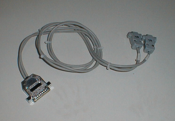 |
Figure 1 (click to enlarge) |
Figure 1 shows the completed cable, from parallel port to joystick ports. This is not the simplest cable to build as it involves splitting to two ports, and soldering resistors.
Due to the physical distance between your PC and C64, determine what length of cable you need first. My parts list assumes about 6 feet, but if its longer then get longer cables.
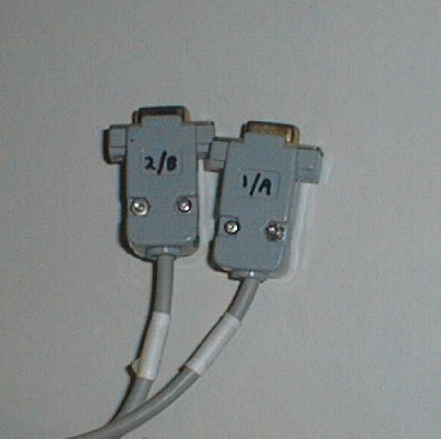 |
Figure 2 (click to enlarge) |
Figure 2 shows the joystick ends. Note how I have labelled them so as to not confuse them. They must be plugged into the right ports, as per the numbering, or you will likely blow up something. I've even labelled the cables, just to be safe.
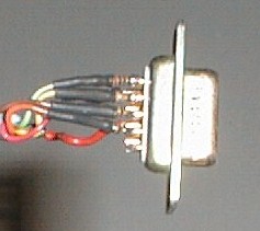 |
Figure 3 (click to enlarge) |
Figure 3 shows the installed resistors on the joystick port connector. Note how I put heat shrink tubing on the legs of the resistors so they won't short together.
I used 1/8 watt resistors scavenged from an old PC monitor board. These are about half the size of the 1/4 watt variety, and worked better in this situation as there's not too much room once you put the hood on the connector.
Cable connector chart
| DB25 PC Parallel | Joystick Ports |
Joystick Pins |
|---|---|---|
2 |
1 |
--xxx-- 1 (JOYA0) |
3 |
1 |
--xxx-- 2 (JOYA1) |
4 |
1 |
--xxx-- 3 (JOYA2) |
5 |
1 |
--xxx-- 4 (JOYA3) |
6 |
1 |
--xxx-- 6 (BUTTON A/LP) |
10 |
2 |
4 (JOYB3) |
11 |
2 |
6 (BUTTON B) |
12 |
2 |
3 (JOYB2) |
13 |
2 |
2 (JOYB1) |
15 |
2 |
1 (JOYB0) |
25 |
1, 2 |
8 (GND) |
In the above chart, the marking "--xxx--"indicates to install a resistor inline to the pin on the the connector.
Email the author: Peter Schepers | Last updated: Mar 17, 2009