Building the XAP1541 Serial+Parallel Y Cable
Parts needed: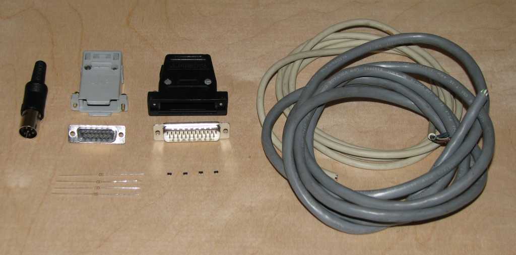
- (4) BSV52 surface mount transistors*
- (4) 4.7K 1/8 watt axial resistors
- Some 22 or 24 gage junk wire, preferrably black and red colors, to be used for the transistor/resistor module building.
- Some 3/32" or 1/8" heat shrink for the transistor/resistor modules (which must be built)
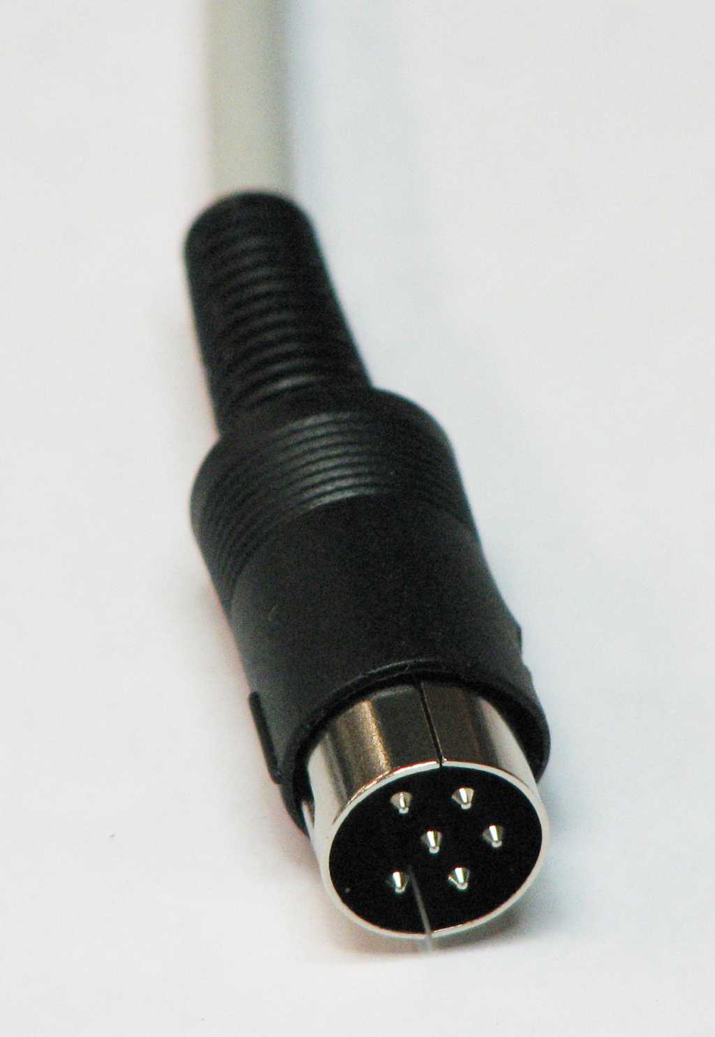
- (1) 6-pin DIN male plug with cover (1541 serial port)
- (1) DB15 male plug + hood
- (1) DB25 male plug + hood
- (1) 6' or 1.8 meters (max) 8 conductor unshielded cable (for parallel connection)
- (1) 6' or 1.8 meters (max) 4 conductor shielded cable (for serial connection). These two cables should be the same length, but only for cosmetic reasons.
*Note: in the above parts picture there are 4 small black parts beneath the DB25 connector. These are the BSV52 transistors, and yes they are that small! Visit the ports, parts & pinouts page for a descriptions of all the above parts.
Tools needed:
- Multi-meter with DIODE checker
- Soldering iron
- Solder
- Wire cutters
- Wire strippers
- Various screw drivers
- Small vice
- Heat shrink gun
- A lighted magnifier is very handy
This cable is called an "active serial-parallel" cable because it uses active components like transistors (and resistors), but these components also make it the most difficult to build. It is a combination of the XA (serial) and XP (parallel) cables, thus it allows high speed transfers but you must have the C= parallel option installed in your disk drive in order to take advantage of the parallel portion of the cable. This cable has the same pinouts as the XMP1541, and works under DOS, but it is also a multi-task cable and works under multi-tasking OS's like Windows or GNU/Linux using the proper software like OpenCBM. It is also the most compatible cable with present day parallel ports and modes, and is designed to work where the X, XE and XM cables fail. The XA cable requires inverted logic to drive it compared to the other cables due to the use of transistors. This cable works with Star Commander and MNIB/NIBTOOLS.
If you're not sure this is the right cable for you, see my cable picking guide to check.
XA cable copyright Michael Klein & Nicolas Welte, 2000
XP cable copyright Joe Forster/STA, 1997
Step 1: Build the transistor/resistor modules
This is the hardest step simply because of the small size of the surface mount transistors being used. You will need magnifiers or have really good eyes to work with these, and they are very easy to lose! It is also very easy to confuse the base and emitter legs because the transistor looks very similar from the bottom and top. The bottom is where the legs bend down towards.
The following construction process may seem complicated but once you build a few of the modules it becomes much easier. The lengths of the lead wires are critical to making this work well because if they are too short then the modules start getting stressed. If this procedure seems too daunting, then I strongly recommend you buy a cable instead.
- Position the transistor in the left side of a vice so that the single leg side is down, and the bottom is towards you. This puts the base leg on the upper left, the emitter on the upper right and the collector on the bottom.
- Cut the end off one of the 4.7k 1/8 watt resistor, leaving about 1/4" (5 mm) of lead.
- Make a very small loop on the just-cut end and solder it to the base leg of the transistor. Be sure to pull the resistor to the left (away from the transistor) so that you still have room to attach the wire to the emitter leg without shorting the two together. The other lead of the resistor is what will be soldered to one of the cups on the DB25.
- Remove the transistor from the vice and place it back in the vice being held by the long resistor lead, with the single soldered pin on the transistor to the top. This puts the emitter leg of the transistor to the upper left.
- From the junk cable, cut a black wire to about 1.5" (3.5 cm), strip both ends to about 1/4" (5 mm), twist and tin both ends of the wire.
- Make a small loop in one end of the black wire and solder it onto the emitter leg of the transistor. This is the ground connection.
- Remove the transistor from the vice again and turn it over, once again clamping it in the vice by the resistor lead, so that the collector leg on the transistor is now to the top.
- From the junk cable, cut a red wire to about 1.5" (3.5 cm), strip both ends to about 1/4" (5 mm), twist and tin both ends of the wire.
- Make a small loop in one end of the red wire and solder it onto the collector leg of the transistor. This is the signal wire from the 1541 serial port.
- Using a multimeter on diode check and the red meter lead on the long lead of the base resistor, measure the following wire combinations:
- From resistor lead to black wire, meter reading should be 1.6 to 1.7
- From resistor lead to red wire, meter reading should be 1.6 to 1.7
- From red wire to black wire, meter reading should be open (infinite)
- There should not be a short between any wire/lead combination.
- Cut a piece of heat shrink so that it just fits over the length of the resistor/transistor module, likely about 1/2" (1.2 cm). Slip it over the end with the two wires (not the resistor end) and fit it over the module, covering the critical parts especally with leg solder. Use a heat gun (not a lighter, it's too hot) to shrink the wrap down so it's tight and won't slip. The heat shrink should hold the entire module together very tightly.
- Now repeat these instructions three more times to complete the four modules!
 |
 |
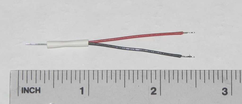 |
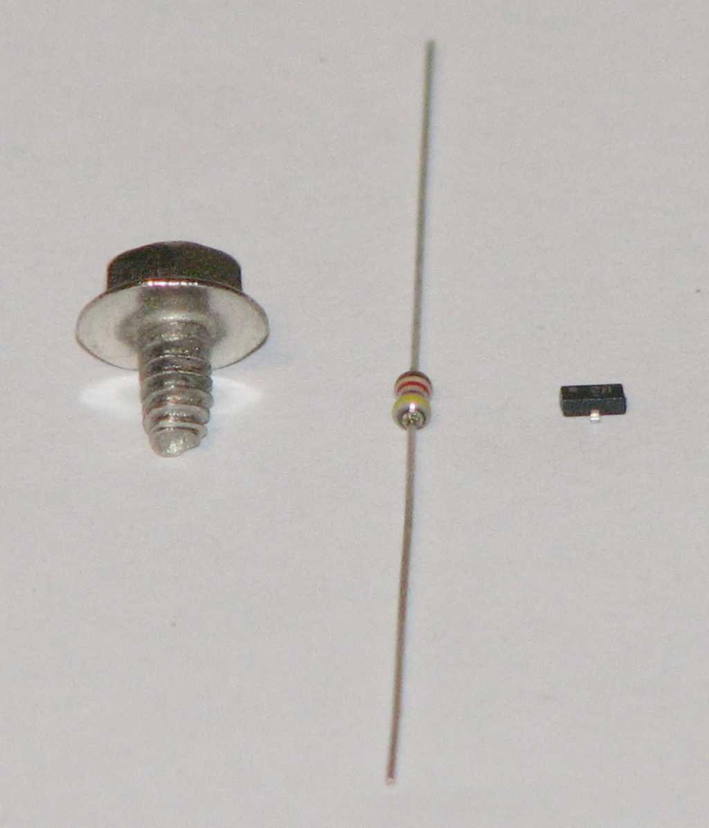
| For a size comparison, the screw is a standard computer case screw. | The completed module, without heat shrink. | The completed module, with heat shrink, and a ruler to see the measurements. |
Step 2: Prep the DIN6 plug and attach the wires
- Pre-solder pins 2 to 6 on the DIN6 so that the wires will solder better. Some of the DIN6 plugs are very sensitive to heat and the plastic holding the pins melts fast. If the plug appears to have this problem, you can insert the plug into an unused 1541 serial port and use it as a heat sink.
- Strip off one end of the 4 conductor cable about 1/2" (1.2 cm) back. You will want the wires this short as the DIN6 connectors don't have a lot of room for extra wire length.
- Strip the individual wires back about 1/8" (3 mm) to expose bare wire.
- Twist and tin the wires and ground shield wire
- Solder these 5 conductors into the cups on pins 2 to 6 of the 6-pin round DIN plug, making sure the outer ground shield goes to pin 2 (GND). Mark down the wire colors going to each DIN post for later. Pin 1 on the DIN6 is not used.
- DIN6 pin-to-wire color chart:
- Pin 2 - ___________
- Pin 3 - ___________
- Pin 4 - ___________
- Pin 5 - ___________
- Pin 6 - ___________
- DIN6 pin-to-wire color chart:
- Fit the completed DIN end into its shield, crimp the cable into the tail clamp, and put the outer sheath over the shield, completing the DIN end.
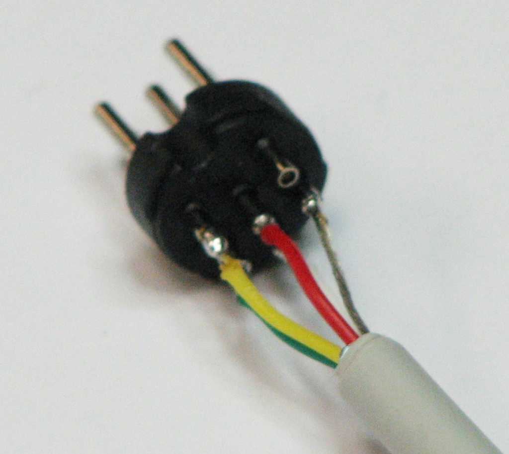 |
 |
| Wires attached to the DIN plug | The completed DIN6 end |
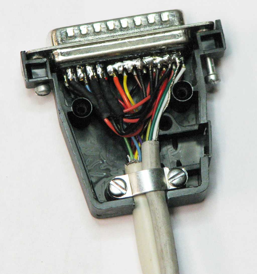
Step 3: Solder the transistor/resistor modules to the DB25
- Trim each module's resistor lead down to 1/4" (1/2 cm)
- Solder a module via the resistor lead to the following pins: 1, 14, 16 and 17.
- Solder the black wires to any of the solder bridge ground pins (18 to 25) (see the first picture below)
- Solder the red wire from the module on pin 1 to pin 13
- Solder the red wire from the module on pin 14 to pin 12
- Solder the red wire from the module on pin 16 to pin 10
- Solder the red wire from the module on pin 17 to pin 11 (see the second picture below)
- It might help to crimp both the black and red wires where they come out of the top of the modules, to reduce stress on the modules.
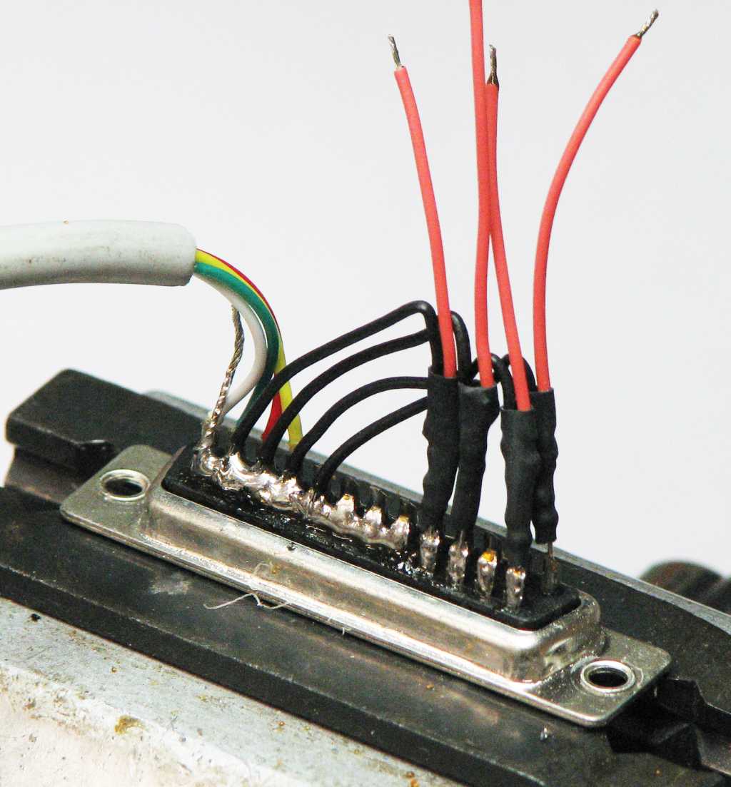 |
 |
| The modules are partially done.. | The modules are all soldered. |
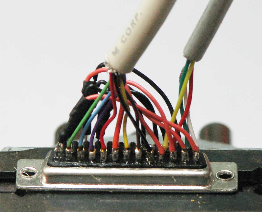
Step 4: Prep the DB25 connector and attach the DIN6 wires
- Strip the other end of the 4 conductor cable back about 3/4" (2 cm)
- Strip each wire back about 1/4" (5 mm) to expose bare wires
- Twist and tin these wires and the ground shield wire
- Solder bridge pins 18 to 25 on the DB25 connector to make the ground strip. It may help to cut and bend a wire so it fits from pin 18 to 25 and solder it to the cups.
- Pre-solder each of the other DB25 solder cups, so that wire insertion and module attachment will be easier later. The only pin not used is pin 15.
- Attach the wires from the 4 conductor cable to the DB25 pins, using the previous color code as a guide.
Going in this pin order will make connections easier.
- DIN6 to DB25 pins...
- 2 to 25
- 5 to 10
- 6 to 11
- 4 to 12
- 3 to 13
- DIN6 to DB25 pins...
 |
 |
| The solder bridge on the DB25 from pins 18 to 25. | The DIN6 wires are attached. |
Step 5: Prep the DB15 connector and attach the wires
- Strip one end of the 8 conductor cable back about 3/4" (2 cm) to expose the wires.
- Strip each wire back about 1/4" (5 mm).
- Twist and tin each wire.
- Pre-solder each cup from pin 1 to 8, so that wire insertion will be easier.
- Attach the 8 wires to pins 1 to 8 on the DB15. Mark down what wire color goes to what pin, for later reference.
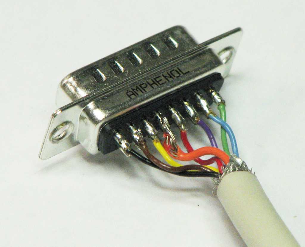 |
| Wires attached to the DB15 |
Note that there is no ground line on this half of the cable. This is because the serial half contains the ground lines and an inclusion of a ground line here could cause a ground loop condition, something which must be avoided. Also, the parallel port add-on on the C= disk drive doesn't contain a ground line for this very reason.
Step 6: Prep the other end of the 8 conductor wire and attach to the DB25
- Strip the other end of the 8 conductor cable back about 3/4" (2 cm) to expose the wires.
- Strip each wire back about 1/4" (5 mm).
- Twist and tin each wire.
- Attach each wire to the DB25, using the color code from the previous step on the DB15.
- DB15 to DB25 pins...
- 1 to 2
- 2 to 3
- 3 to 4
- 4 to 5
- 5 to 6
- 6 to 7
- 7 to 8
- 8 to 9
- DB15 to DB25 pins...
 |
| The completed DB25 end. Crowded with the modules in there. |
Step 7: Check the cable
- Using a multi-meter on DIODE (continuity) check, measure between the pins on the chart below.
There should be a short between each of the pins from one connector to the other:
- Verify that pins 18 through 25 on the DB25 are shorted together
- DIN6 to DB25 wires
- 2 to 25
- 3 to 13
- 4 to 12
- 5 to 10
- 6 to 11
- DB15 to DB25 wires
- 1 to 2
- 2 to 3
- 3 to 4
- 4 to 5
- 5 tp 6
- 6 to 7
- 7 to 8
- 8 to 9
- For the transistor/resistor modules, use the multimeter on DIODE check again and check between the following pins
on the DB25:
- Red lead on pin 1 to pin 13 should be 1.6 to 1.7 volts
- Red lead on pin 1 to ground strip (pins 18-25) should be 1.6 to 1.7 volts
- Red lead on pin 14 to pin 12 should be 1.6 to 1.7 volts
- Red lead on pin 14 to ground strip (pins 18-25) should be 1.6 to 1.7 volts
- Red lead on pin 16 to pin 10 should be 1.6 to 1.7 volts
- Red lead on pin 16 to ground strip (pins 18-25) should be 1.6 to 1.7 volts
- Red lead on pin 17 to pin 11 should be 1.6 to 1.7 volts
- Red lead on pin 17 to ground strip (pins 18-25) should be 1.6 to 1.7 volts
- If any of the above module readings are wrong, then one of the modules might have the base and emitter wires swapped as it's a very easy mistake to make. It will have to be removed and fixed..
Cable pinout chart
DIN6 (male) |
DB15 (male) |
DB25 (male) |
|---|---|---|
2 (GND)
|
18 to 25 (GND)
|
|
3 (ATN)
|
13 (SELECT)
|
|
4 (CLK)
|
12 (PAPER END)
|
|
5 (DATA)
|
10 (ACK)
|
|
6 (RESET)
|
11 (BUSY)
|
|
1 (PB0) |
2 (DATA0) |
|
2 (PB1) |
3 (DATA1) |
|
3 (PB2) |
4 (DATA2) |
|
4 (PB3) |
5 (DATA3) |
|
5 (PB4) |
6 (DATA4) |
|
6 (PB5) |
7 (DATA5)
|
|
7 (PB6) |
8 (DATA6)
|
|
8 (PB7) |
9 (DATA7)
|
|
18 to 25 shorted |
The four transistor/resistor modules in the DB25 are attached like this:
Module 1: resistor lead to pin 1, red wire to pin 13, black wire to ground strip (solder bridge on pins 18 to 25)
Module 2: resistor lead to pin 14, red wire to pin 12, black wire to ground strip (solder bridge on pins 18 to 25)
Module 3: resistor lead to pin 16, red wire to pin 10, black wire to ground strip (solder bridge on pins 18 to 25)
Module 4: resistor lead to pin 17, red wire to pin 11, black wire to ground strip (solder bridge on pins 18 to 25)
Step 8: Finish the cable. Mount the DB ends in their hoods
- Mount both the DB15 and the DB25 connectors in their respective hoods. If the modules or wires need to be squished a bit to fit, it should be OK to do so.
- Test the cable to be sure it works. Since this is a serial+parallel cable, you can use both Star Commander and MNIB/NIBTOOLS to test it.
 |
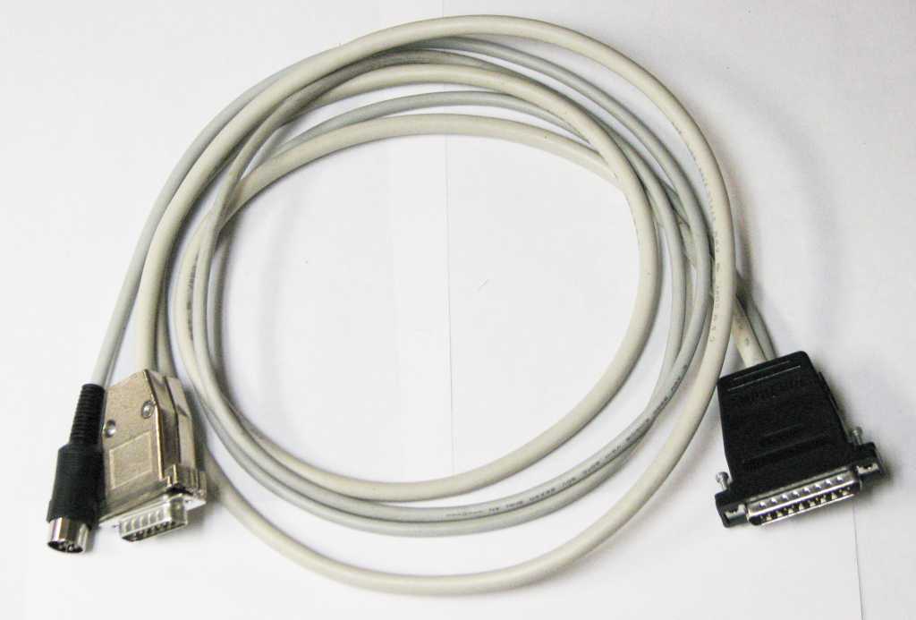 |
| Fitting the DB25 into the hood. | The completed XAP cable. |
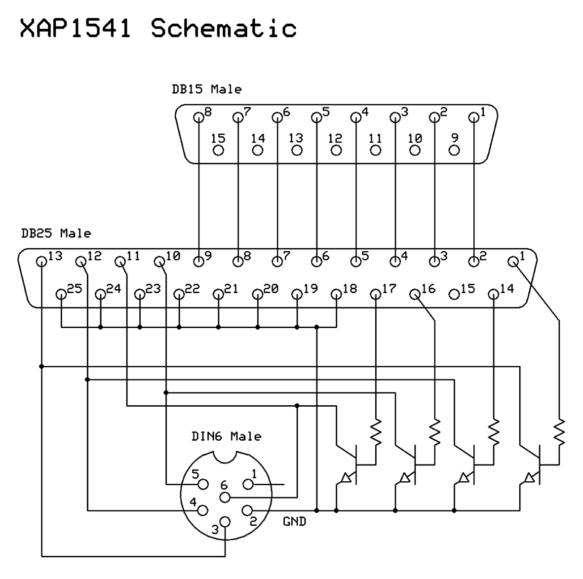 |
Schematics drawn using ExpressPCB, a free and excellent solution which also supports PC board layout editing.
Email the author: Peter Schepers | Last updated: Mar 17, 2009