Building the XM1541 Serial Cable
Parts needed: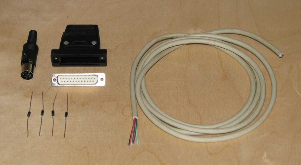
- (4) 1N5819 Schottky diodes
- Some 3/32" or 1/16" heat shrink for the diode legs
- (1) 6-pin DIN male plug with cover (1541 serial port)
- (1) DB25 male plug + hood
- (1) 6' or 1.8 meters (max) 4 conductor shielded cable (for serial connection)
Visit the ports, parts & pinouts page for a descriptions of all the above parts.
Tools needed:
- Multi-meter with DIODE checker
- Soldering iron
- Solder
- Wire cutters
- Wire strippers
- Various screw drivers
- Small vice
- Heat shrink gun
- A lighted magnifier is very handy
This is called a "multi-task serial" cable in that it not only works under DOS, but also under multi-tasking OS's such as Windows or GNU/Linux using the proper software like OpenCBM. It uses the same pinout as the XA1541 cable and is compatible with present day parallel ports and modes with a few exceptions. With the switch of two wires, you would have an XE1541 cable. Like the X1541, it is not a difficult cable to build requiring only 4 Schottky diodes instead of the transistor/resistor modules that the XA1541 uses. This cable works with Star Commander, but not with MNIB/NIBTOOLS as you must also have a parallel cable and a parallel port on the 1541/1571 drive.
If you're not sure this is the right cable for you, see my cable picking guide to check.
XM cable copyright Michael Klein & Nicolas Welte, 2000
Step 1: Build the diode modules
Just like the resistor/transistor modules for the XA and XAP, this step creates diode/wire-lead modules which are easy to install on the DB25 connector.
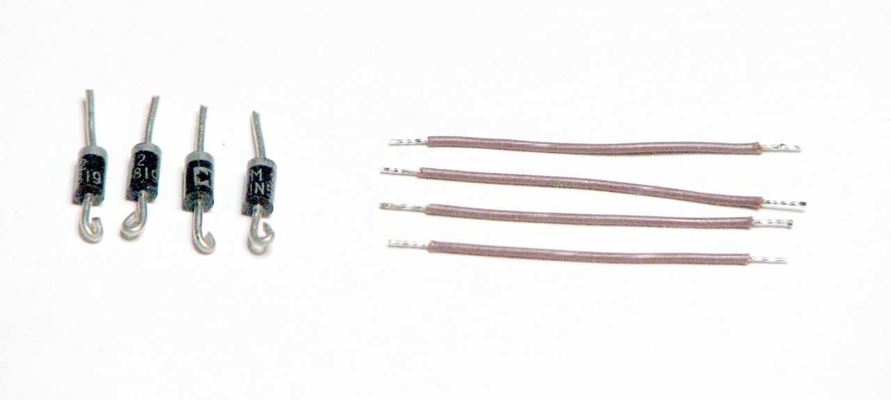 |
First, take the four diodes, cut both ends to about 1/2" (1 cm). Make a small loop in the anodes ends (the ones opposite the ends with the circle all the way around). Strip the wires back about 1/8" (1/2 cm), and twist & tin the wires. |
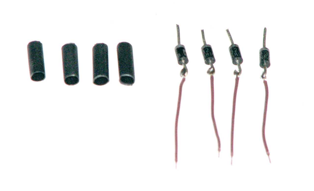 |
Second, make a loop in one end of each wire, hook it to the loop of one diode and solder the two together. Cut some 3/32" or 1/8" heat shrink tubing to about 1/2" (1 cm), enough length to cover the wire/diode solder joint and just go over the end of the diode. The heat shrink prevents the diode legs from shorting to each other when soldered to the DB25. |
 |
Third, place the heat shrink tubing over the solder joint and the end of the diode and shrink it on. The modules are now ready to be used. |
Step 2: Prep the DIN6 plug and attach the wires
- Pre-solder pins 2 to 6 on the DIN6 so that the wires will solder better
- Strip off one end of the 4 conductor cable about 1/2" (1.2 cm) back.
- Strip the individual wires back about 1/8" (3 mm) to expose bare wire.
- Twist and tin the wires and ground shield wire
- Solder these 5 conductors into the cups on pins 2 to 6 of the 6-pin round DIN plug, making sure the outer ground shield goes to pin 2 (GND). Mark down the wire colors going to each DIN post for later. Pin 1 on the DIN6 is not used. Soldering to these pins is not easy, and excess heat can cause the plastic to melt and cause the pin to shift.
- Fit the completed DIN end into its shield, crimp the cable into the tail clamp, and put the outer sheath over the shield, completing the DIN end.
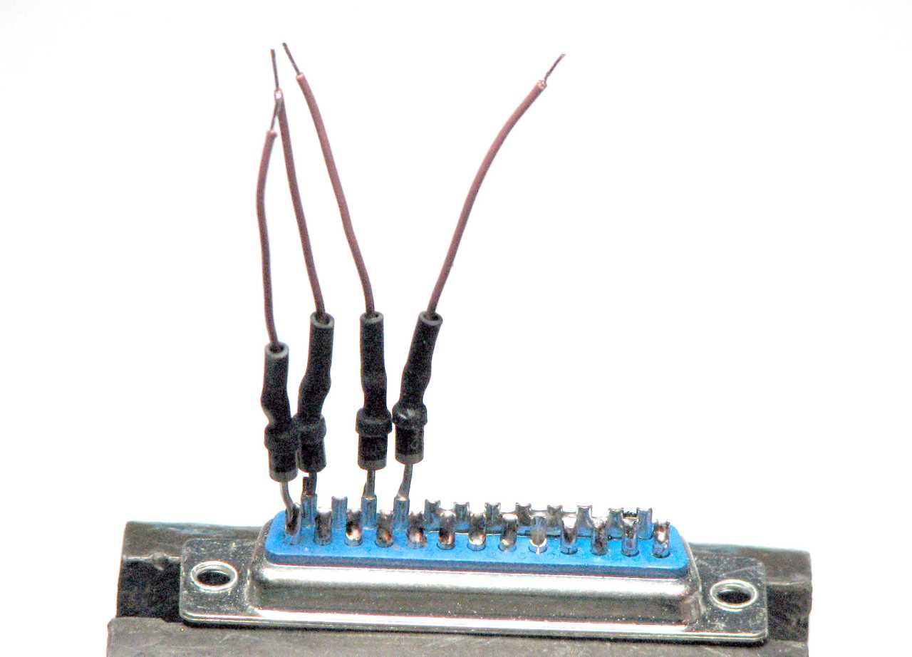
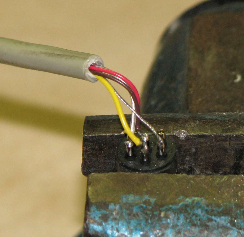 |
Wires attached to the DIN plug. |
Step 3: Prepare the DB25 connector and attach the diode modules
- Pre-solder the DB25 cups 10, 11, 12 & 13 so that the DIN6 wire insertion will be easier.
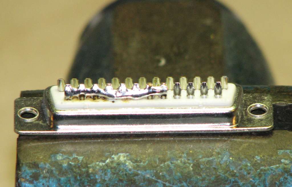
- Solder bridge pins 18 through 25 on the DB25 connector to make the ground strip.
-
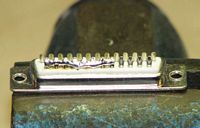
The solder bridge on the DB25 from pins 18 to 25. - Solder a diode (cathode end, the end of the diode without the wire attached) to the pins listed...
- 1
- 14
- 16
- 17
-

The diode modules on the DB25
- Now, bend the wires attached to the diodes and solder the wire to its appropriate pin listed...
- Diode anode to cathode on the DB25 pins... (cathode ---|<--- anode)
- 16 to 10
- 17 to 11
- 14 to 12
- 1 to 13
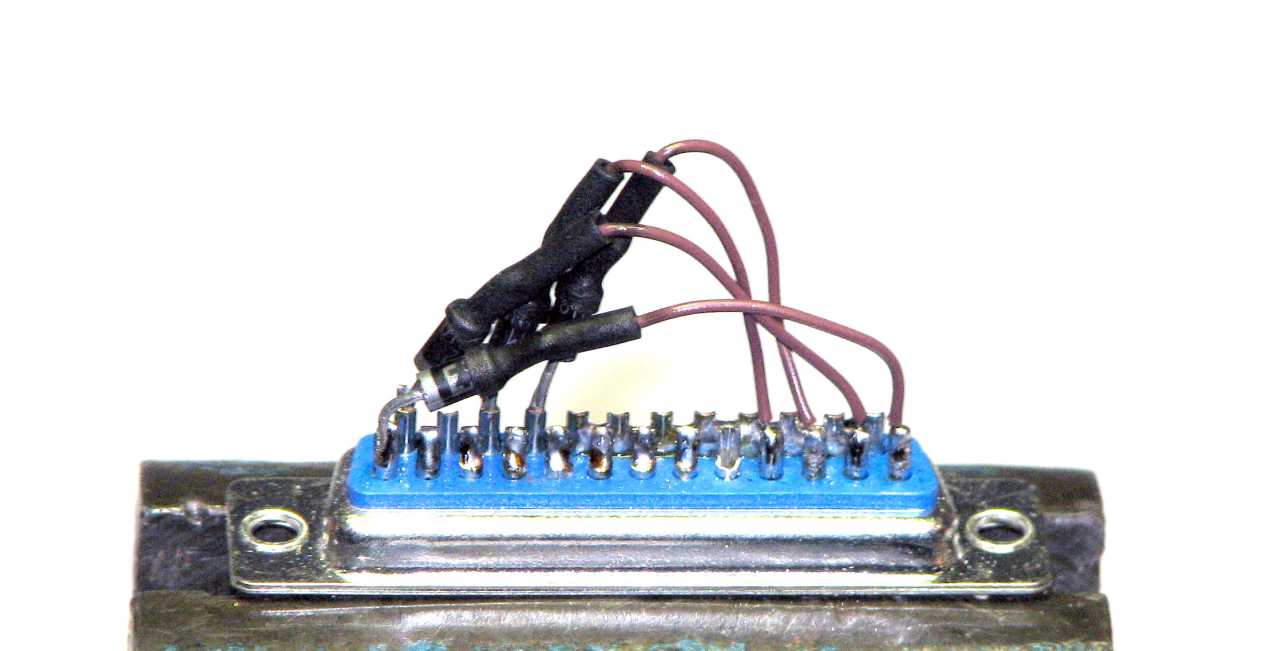
-
The diode modules completely soldered to the DB25
Step 4: Attach the wires from the DIN6 serial connector
- Strip the other end of the 4 conductor cable back about 3/4" (2 cm)
- Strip each wire back about 1/4" (5 mm) to expose bare wires
- Twist and tin the wires and ground shield wire
- Attach the wires from the 4 conductor cable to the DB25 pins, using the previous color code as a guide.
- DIN6 to DB25 pins...
- 2 to 25
- 3 to 13
- 4 to 12
- 5 to 10
- 6 to 11
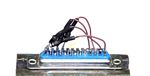
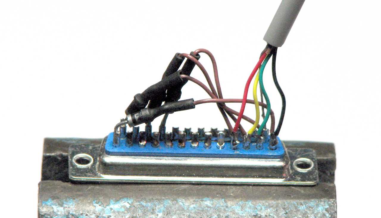
-

All the diode bridges in place, and the DIN6 serial cable is attached. The DB25 end is completed.
Step 5: Check the cable
- Using a multi-meter on DIODE (continuity) check, measure between the pins on the following chart.
- DIN6 to DB25 wires
- DB25 diode bridges
- There should be a short between each of the pins from one connector to the other.
- For the diode bridges on the DB25, you must use the RED (+) lead on the ANODE end of the diode, and BLACK (-) lead on the CATHODE end in order to get a reading. There will not be a short, but rather a small diode drop from .3 to .7 volts.
- Verify that pins 18 through 25 on the DB25 are shorted together.
Cable pinout chart
DIN6 (male) |
DB25 (male) |
|---|---|
2 (GND)
|
18-25 (GND)
|
3 (ATN)
|
13 (SELECT)
|
4 (CLK)
|
12 (PAPER END)
|
5 (DATA)
|
10 (ACK)
|
6 (RESET)
|
11 (BUSY)
|
13 (SELECT) -->|-- 1 (STROBE)
|
|
12 (PAPER END) -->|-- 14 (AUTOFEED) |
|
11 (BUSY) -->|-- 17 (SELECTIN) |
|
10 (ACK) -->|-- 16 (INIT) |
|
18 to 25 shorted |
Step 5: Finish the cable. Mount the DB25 end into the hood
- Mount the DB25 connector into its hood. If the diodes or wires need to be squished a bit to fit, it should be OK to do so.
- Test the cable to make sure it works.
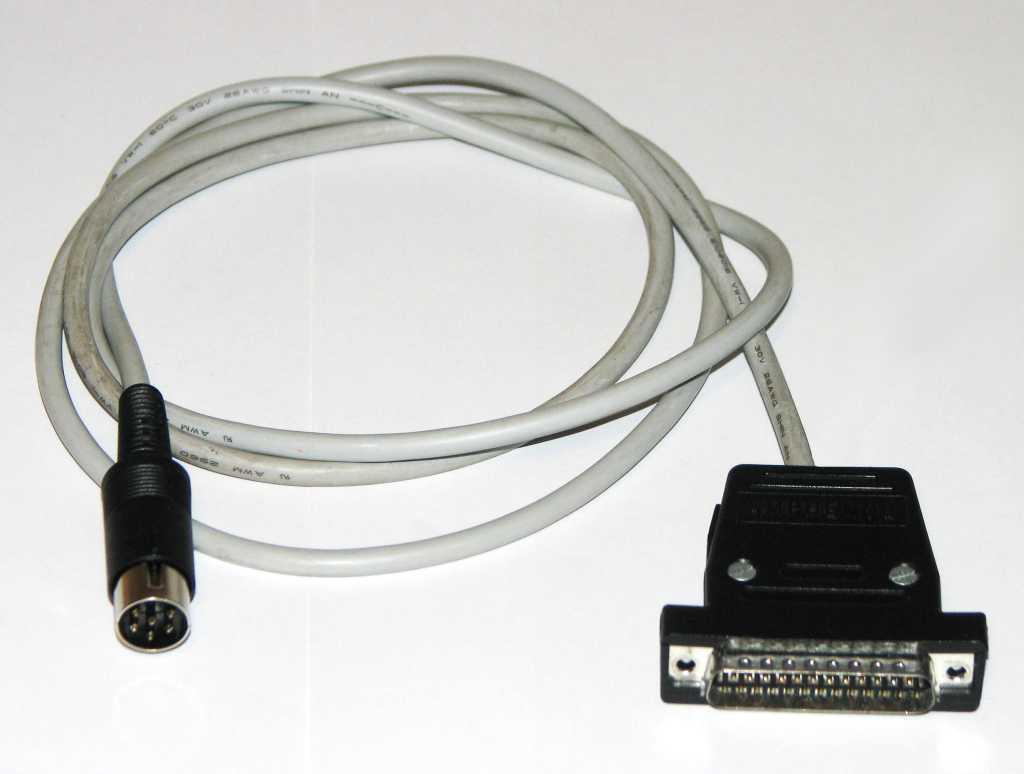 |
The completed XM cable. |
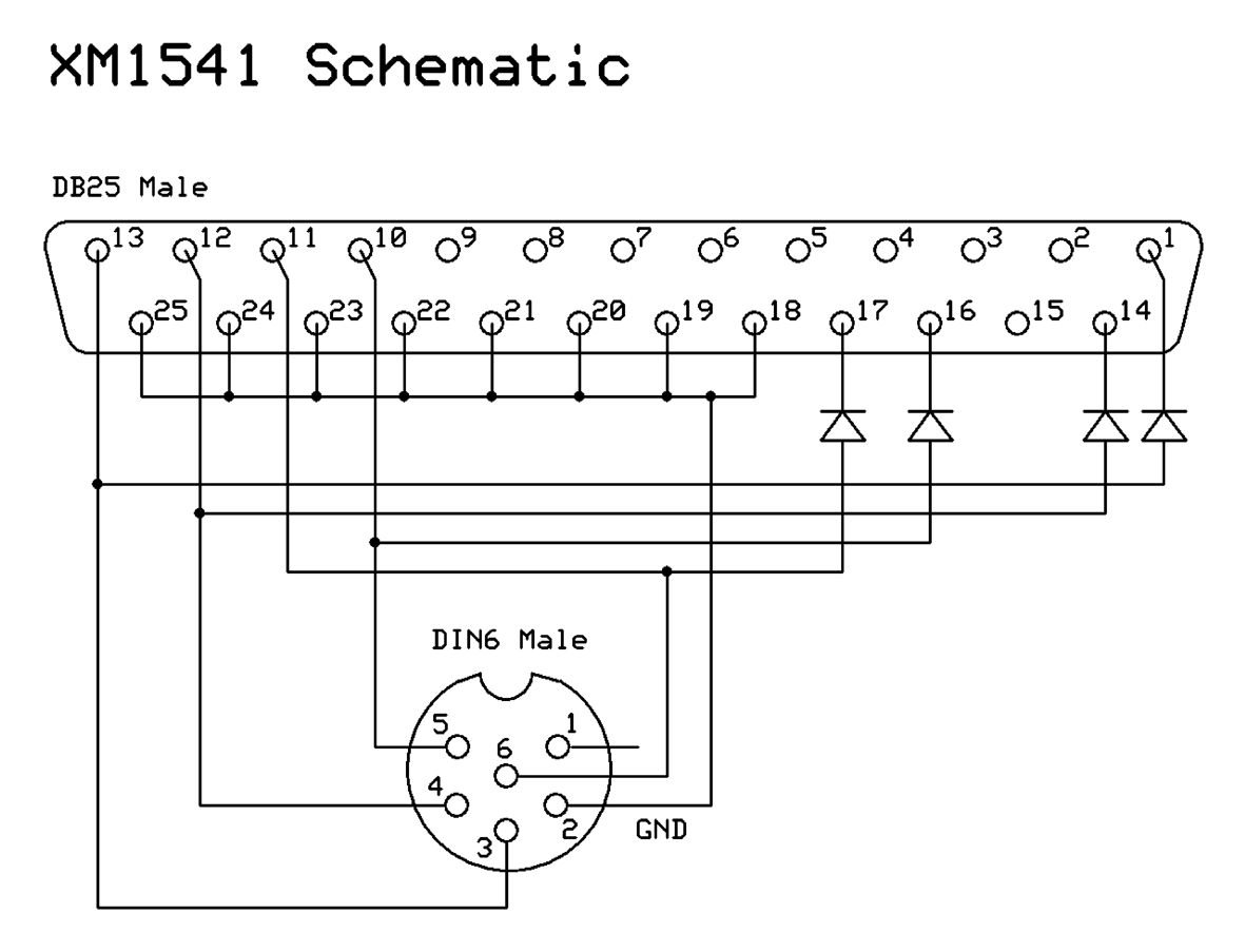 |
Schematics drawn using ExpressPCB, a free and excellent solution which also supports PC board layout editing.
Email the author: Peter Schepers | Last updated: June 8, 2009