Installing the 1571 Parallel Port Option
Parts needed:
Drill, bits and files to make & shape the hole in the 1571 chassis.
Introduction
The 1571 parallel port hooks up to the 6526 or 8521 CIA at position U20. This chip is typically socketed, so the socketed cable should work. All it requires is to remove the power supply, pop out the CIA chip, insert the socketed cable and re-insert the CIA. If the CIA is not socketed either install a socket for the chip or use the soldered cable and solder the port wires directly to the CIA chip (top or bottom of the board). I have yet to see a CIA chip in a 1571 that is not socketed but it is possible.
Warning: when the socketed cable is installed and the CIA is re-inserted into the socket, the corner of the power supply near the CIA chip will rest on the top of the CIA instead of on the riser post. You can glue/add about 1/16" (2 mm) of flat washers to the top of the riser post so the supply won't touch the chip or else don't tighten the screw too much on that corner because you could damage the board from the stress.
If the firmware on your 1571 is older (310654-03 or less) then you likely will have an issue with the drive taking a long time to access 1541 disks after they are inserted. The drive will act as though the head is out of alignment as it attempts to read it. Once they are recognized they will read fine. This issue is fixed with the later ROM version 310654-05 or with JiffyDOS.
I ran into many issues when modding my 1571 for parallel. The door latch pin was loose, the door handle stem was loose, the latch lowering mechanism wasn't pushing the spindle down far enough so the disk wouldn't turn, and the old ROM revision caused initial reading problems. However, when these issues are dealt with, the 1571 is a very fast drive on parallel, feeling about 20% faster than a 1541.
Step 1: Build the internal parallel cable
Click here for the instructions on how to build the internal parallel cable for your 1571 drive.
Step 2: Top case removal
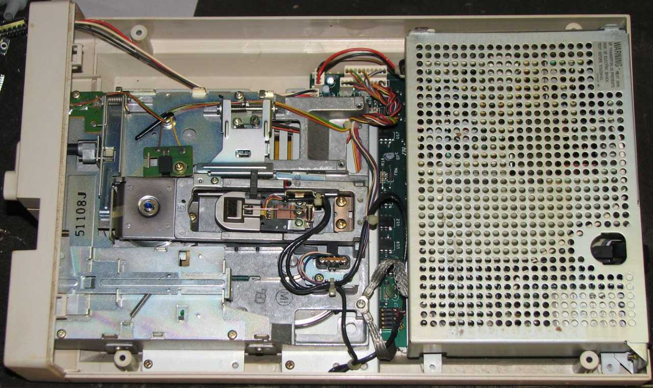 |
First, crack open the 1571 by removing the four bottom screws and taking off the top cover. The drive mechanism is on the left in this picture, and the power supply (with the logic board underneath) is on the right. |
Step 3: Power supply removal
 |
Remove the power supply by removing the four screws, another screw for the grounding strap and the power connector, then lifting out the supply.The 6526 CIA is shown at U20. It is the top-left 40-pin chip in the picture. |
Step 4: Shape a case hole & install cable
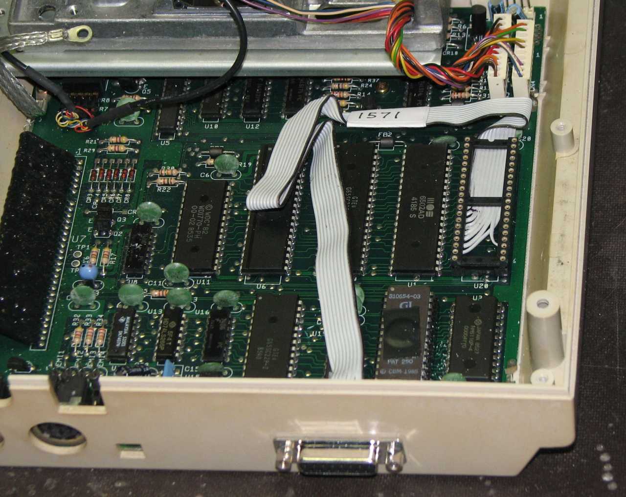 |
You will need to shape a hole in the case somewhere. I chose to install it near the bottom of the board, beneath the power supply. You could run it out the side somewhere, but the power supply does take up quite a bit of room in the rear of the drive and there was room underneath in a specific location shown. Just be sure to remove the board before making case modifications. Once the port is made and the cable & DB15 connector inserted and screwed to the case, remove the 6526, insert the socket in the correct orientation, and then re-insert the 6526 back into the new socket. Flatten the ribbon cable down so it is out of the way of the supply when it is re-installed. Note that the 6526, when sitting up this high, now touches the bottom of the power supply so don't tighten the screw down for that corner too tight. |
Step 5: Close everything up & test
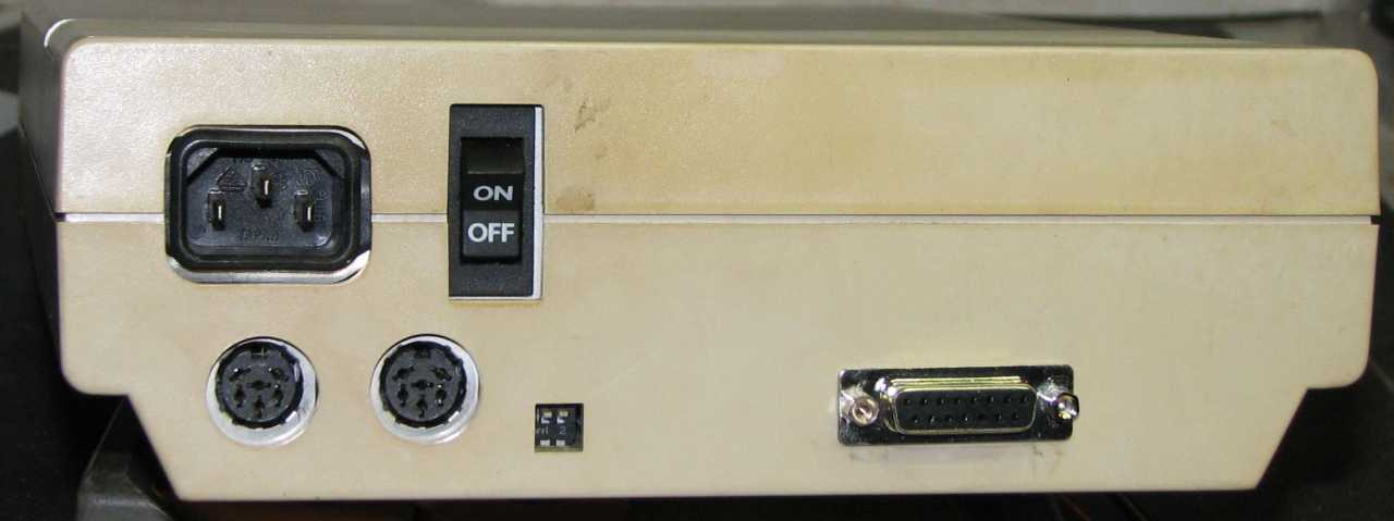 |
This is the completed parallel port installation. I like how the DB15 port is almost inline with the serial ports. |
Email the author: Peter Schepers | Last updated: Sept 8, 2009