Building the X1541 Serial Cable
Parts needed: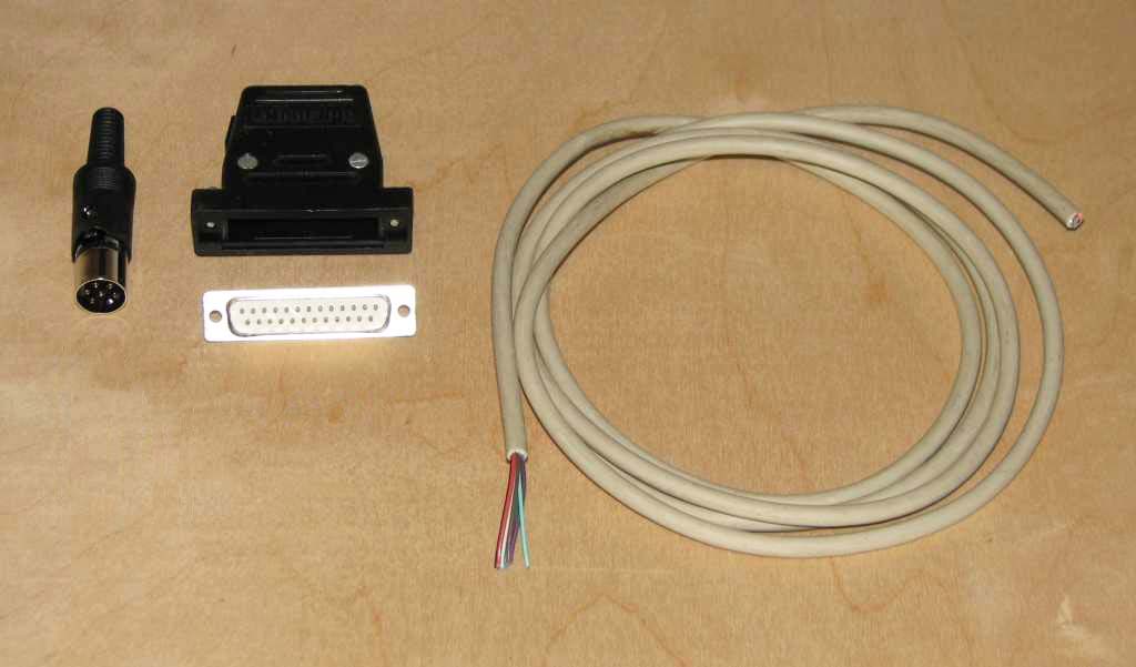
- (1) 6-pin DIN male plug with cover (1541 serial port)
- (1) DB25 male plug + hood
- (1) 6' or 1.8 meters (max) 4 conductor shielded cable (for serial connection)
Visit the ports, parts & pinouts page for a descriptions of all the above parts.
Tools needed:
- Multi-meter with DIODE checker
- Soldering iron
- Solder
- Wire cutters
- Wire strippers
- Various screw drivers
- Small vice
- A lighted magnifier is very handy
The X1541 serial cable is the original PC-to-1541 transfer cable, dating back to 1992. It was designed for parallel ports of the day, which were standard (normal) or PS/2. It utilized the bidirectional nature of the control lines which present-day ECP and EPP ports don't have. Present day ports, even though they claim to be able to emulate PS/2 or standard, simply won't work due to hardware-level implimentation problems. This restricts the cable to vintage systems of 486 and older.
Even though this cable is the easiest to build, requires no extra components like diodes (XE/XEP, XM/XMP) or transistor/resistor modules (XA/XAP) and has the most software support, it is very dated and only works under DOS. This cable is meant for very old hardware, and I do not recommend building one unless you also have such hardware. This cable works with Star Commander and 64HDD, but not MNIB/NIBTOOLS.
If you're not sure this is the right cable for you, see my cable picking guide to check.
Cable copyright Leopoldo Ghielmetti, 1992
Step 1: Prep the DIN6 plug and attach the wires
- Pre-solder pins 2 to 6 on the DIN6 so that the wires will solder better
- Strip off one end of the 4 conductor cable about 1/2" (1.2 cm) back.
- Strip the individual wires back about 1/8" (3 mm) to expose bare wire.
- Twist and tin the wires and ground shield wire
- Solder these 5 conductors into the cups on pins 2 to 6 of the 6-pin round DIN plug, making sure the outer ground shield goes to pin 2 (GND). Mark down the wire colors going to each DIN post for later. Pin 1 on the DIN6 is not used.
- Fit the completed DIN end into its shield, crimp the cable into the tail clamp, and put the outer sheath over the shield, completing the DIN end.
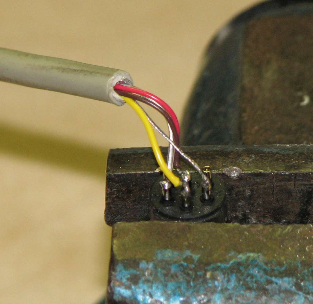 |
| Wires attached to the DIN plug. |
Step 2: Prep the DB25 connector and attach the DIN6 wires
- Strip the other end of the 4 conductor cable back about 3/4" (2 cm)
- Strip each wire back about 1/4" (5 mm) to expose bare wires
- Twist and tin the wires and ground shield wire
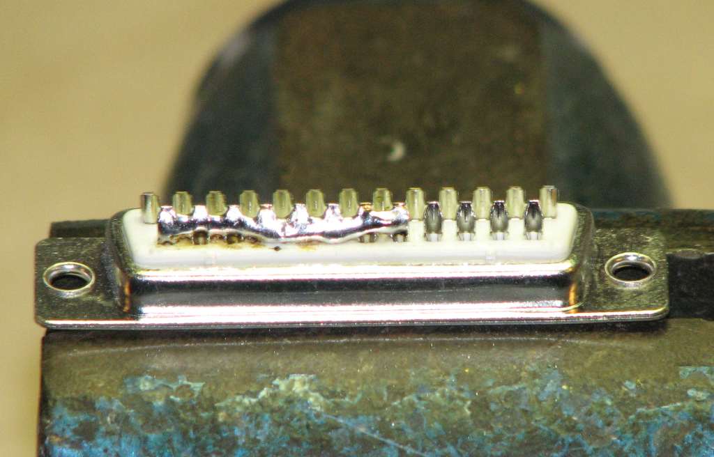
- Solder bridge pins 18 to 25 on the DB25 connector to make the ground strip. It may help to cut and bend a wire so it fits from pin 18 to 25 and solder it to the cups.
- Pre-solder DB25 cups 1, 14, 16 & 17 so that DIN6 wire insertion will be easier.
- Attach the wires from the 4 conductor cable to the DB25 pins, using the previous color code as a guide.
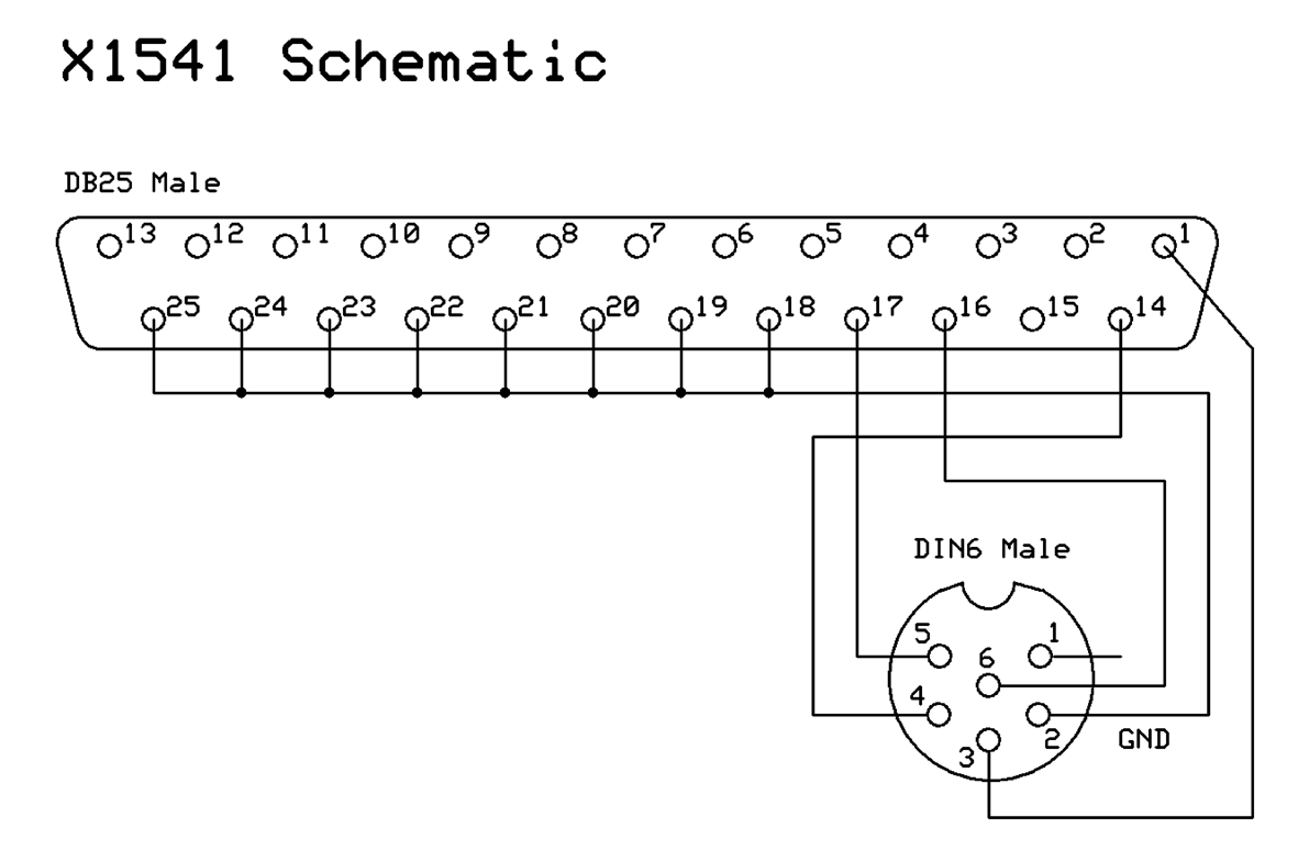
- DIN6 to DB25 pins...
- 2 to 18
- 3 to 1
- 4 to 14
- 5 to 17
- 6 to 16
 |
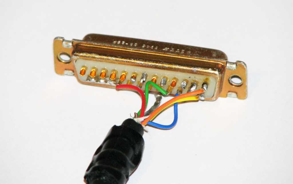 |
| The solder bridge on the DB25 from pins 18 to 25. | The DIN6 wires attached to the DB25. Note that this is an old photo and it is not completely correct so don't compare your cable to this one. |
Step 3: Check the cable
- Using a multi-meter on DIODE (continuity) check, measure between the pins on the chart below. There should be a short between each of the pins from one connector to the other.
- DIN6 to DB25 wires
- Verify that pins 18 through 25 on the DB25 are shorted together.
Cable pinout chart
DIN6 (male) |
DB25 (male) |
|---|---|
2 (GND)
|
18-25 (GND)
|
3 (ATN)
|
1 (STROBE)
|
4 (CLK)
|
14 (AUTO FEED)
|
5 (DATA)
|
17 (SELECT IN)
|
6 (RESET)
|
16 (INIT)
|
18 to 25 shorted |
Step 4: Finish the cable. Mount the DB25 end into the hood
- Mount the DB25 connector into its hood. If the wires need to be squished a bit to fit, it should be OK to do so.
- Test the cable to make sure it works.
 |
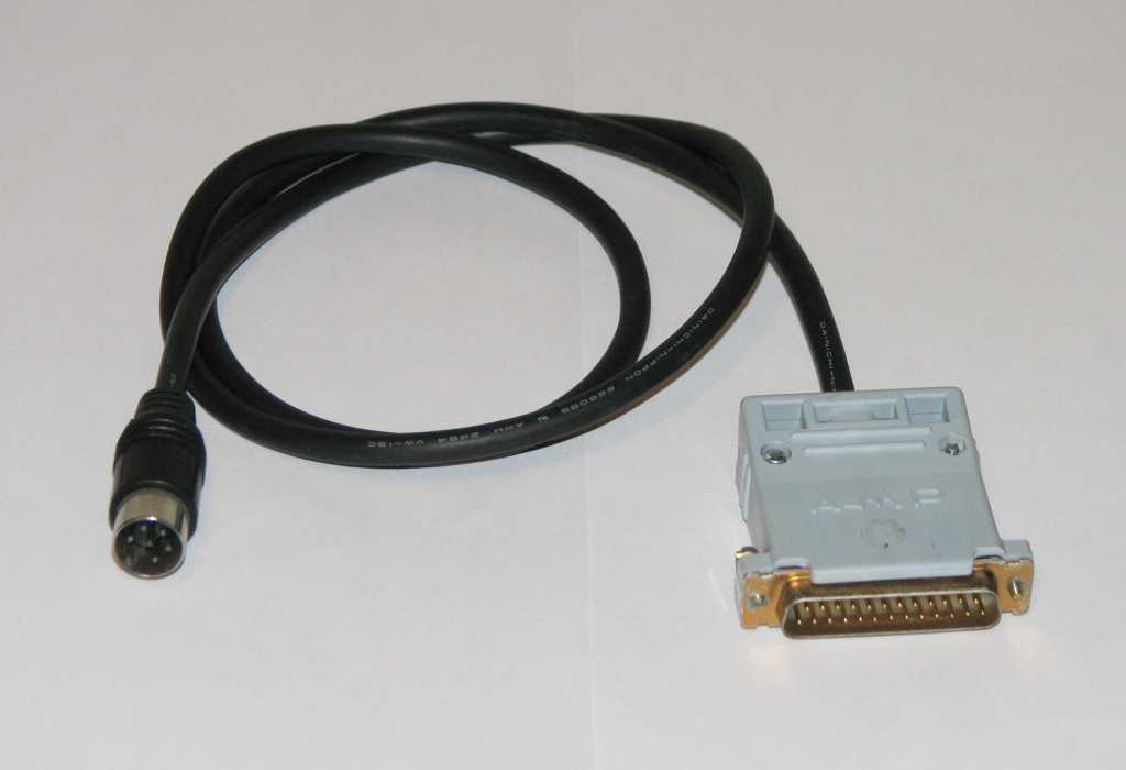 |
| The DB25 mounted in the hood. (Once again, this is an old photo and is not correct.) | The completed X cable. |
 |
Schematics drawn using ExpressPCB, a free and excellent solution which also supports PC board layout editing.
Email the author: Peter Schepers | Last updated: Sept 12, 2011