Building the XH1541 Parallel Cable
Parts needed: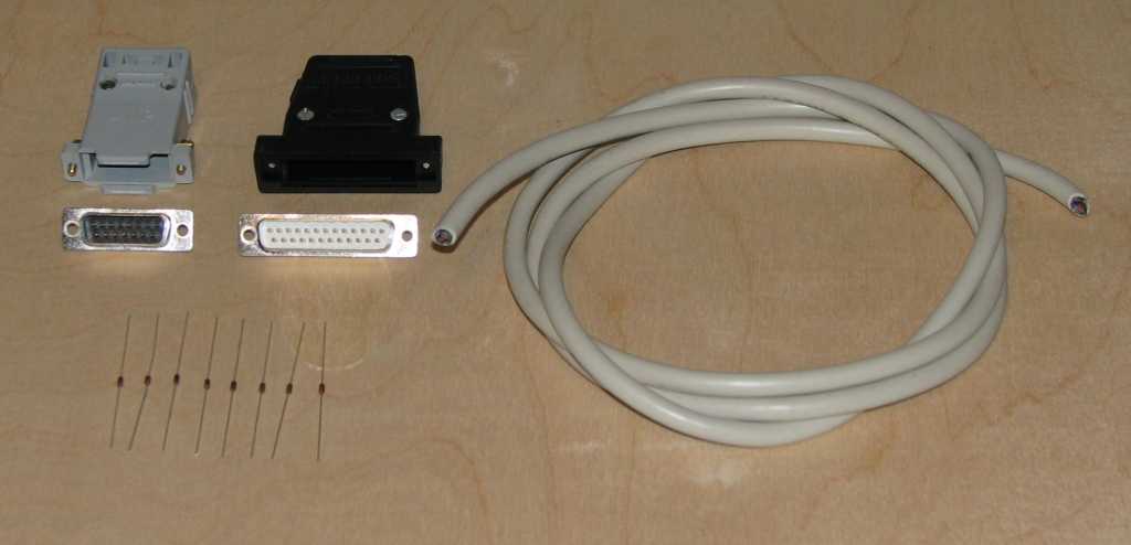
- (8) 1N4148 small signal diodes
- Some 3/32" or 1/16" heat shrink tubing for the diodes
- (1) DB15 male plug + hood
- (1) DB25 male plug + hood
- (1) 6' or 1.8 meters (max) 8 conductor unshielded cable (for parallel connection)
Visit the ports, parts & pinouts page for a descriptions of all the above parts.
Tools needed:
- Multi-meter with DIODE checker
- Soldering iron
- Solder
- Wire cutters
- Wire strippers
- Various screw drivers
- Small vice
- A lighted magnifier is very handy
This is called a "hybrid parallel-only" cable, and it requires the use of a companion serial cable. It is compatible with older parallel ports (standard and PS/2) and thus doesn't work on contemporary hardware. It is a semi-parallel cable (full parallel one way, half-parallel the other) thus allows for limited high speed transfers. You must have the C= parallel option installed in your disk drive in order to use this cable. Due to its pinout and more complex construction requiring eight diodes, it can only be combined with the X1541 to make a XXH1541, or on a system with two parallel ports which it can then be combined with any of the serial cables. It is not recommended to build this cable or the XXH variant due to its limited usefulness, software support and its requirement for older parallel ports. Instead, look at the XM1541, XMP1541, XA1541 or XAP1541 for better options. This cable only works with Star Commander.
If you're not sure this is the right cable for you, see my cable picking guide to check.
Since I have never built this cable, no pictures are possible and thus the following building instructions have not been tested.
XH cable copyright Bigfoot, 1997
Step 1: Prep the DB15 connector and attach the diodes and wires
This process splits the installation of the diodes into 2 groups of 4, one group in the DB15 and one in the DB25. This alleviates some space issues in the DB25 if all 8 diodes were installed there.
- Strip one end of the 8 conductor cable back about 3/4" (2 cm) to expose the wires.
- Cut four of the wires about 1/3" (1 cm) shorter & strip them back about 1/4" (5 mm)
- Strip the other four wires back 1/4" (5 mm)
- Twist and tin all the wires
- Cut each end of four of the diodes leads back to 1/4" (5 mm) from the diode body
- Attach the cathodes to the wires
- Put a 1/2" (1 cm) piece of heat shrink over each of the sections where the wires and diodes were soldered together. You can cover part of the diode if necessary.
- Use a heat shrink gun to shrink the wrap onto the wires & diodes.
- Pre-solder the DB15 cups from pins 1 to 8 so the diode legs and wires attach easier.
- Attach these diode leads to pins 5 through 8.
- Attach the remaining 4 wires to pins 1 through 4
- Mark down what wire color goes to what pin on the DB15 (through the diodes if that's the case), for later use.
Note that this cable contains no ground line and requires the use of the companion X1541 cable to provide the ground. A ground line in this cable could cause a ground loop condition, something which must be avoided. Also, the parallel port add-on to the C= disk drive doesn't contain a ground line for this very reason.
Step 2: Prep the other end of the 8 conductor wire and attach to the DB25
- Strip the other end of the 8 conductor cable back about 3/4" (2 cm) to expose the wires.
- Strip each wire back about 1/4" (5 mm).
- Twist and tin all the wires.
- Solder bridge pins 18 to 25 on the DB25 connector to make the ground strip. It may help to cut and bend a wire so it fits from pin 18 to 25 and solder it to the cups.
- Pre-solder the DB25 pins 2 through 13.
- Attach the first group of 4 wires (from the DB15 through the diodes) to pins on the DB25
- 5 to 6
- 6 to 7
- 7 to 8
- 8 to 9
- Attach the second group of 4 wires from the DB15 to the DB15
- 1 to 13
- 2 to 12
- 3 to 10
- 4 to 11
- Solder 4 diodes to DB25 pins 2 through 5, cathodes to the pins
- Cover these diodes with heat shrink, except for 1/4" (5 mm) on the unconnected end.
- Use the heat shrink gun to shrink the wrap on the diodes.
- Attach the other end of the diode to the following pins
- 2 to 13
- 3 to 12
- 4 to 10
- 5 to 11
Step 3: Check the cable
- Using a multi-meter on DIODE (continuity) check, measure between the pins on the chart below. There should be a short between each of the pins from one connector to the other..
- DB15 to DB25 wires (1 to 13, 2 to 12, 3 to 10 & 4 to 11)
- With the red meter lead on the DB15 pins (anode of the diodes), measure the diodes from the DB15 to the DB25
- 1 to 2
- 2 to 3
- 3 to 4
- 4 to 5
- 5 to 6
- 6 to 7
- 7 to 8
- 8 to 9
- Verify that pins 18 through 25 on the DB25 are shorted together. Note that these are not connected to any other ground.
Cable pinout chart
DB15 (male) |
DB25 (male) |
|---|---|
1 (PB0) |
-->|-- 2 (DATA0) |
2 (PB1) |
-->|-- 3 (DATA1) |
3 (PB2) |
-->|-- 4 (DATA2) |
4 (PB3) |
-->|-- 5 (DATA3) |
5 (PB4) |
-->|-- 6 (DATA4) |
6 (PB5) |
-->|-- 7 (DATA5) |
7 (PB6) |
-->|-- 8 (DATA6) |
8 (PB7) |
-->|-- 9 (DATA7)
|
1 (PB0) |
13 (SELECT) |
2 (PB1) |
12 (PAPER END) |
3 (PB2) |
10 (ACK) |
4 (PB3) |
11 (BUSY) |
18 to 25 shorted
|
Step 4: Finish the cable. Mount the DB ends in their hoods
- Mount both the DB15 and the DB25 connectors in their respective hoods. If the wires or diodes need to be squished a bit to fit, it should be OK to do so.
- Test the cable to make sure it works.
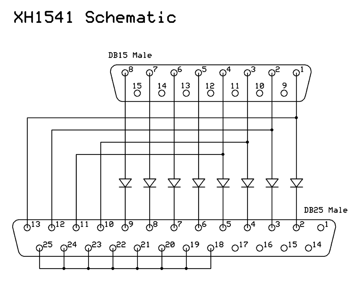 |
Schematics drawn using ExpressPCB, a free and excellent solution which also supports PC board layout editing.
Email the author: Peter Schepers | Last updated: Mar 17, 2009