Building the XMP1541 Serial+Parallel Y Cable
Parts needed: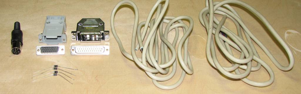
- (4) 1N5819 Schottky diodes
- Some 3/32" or 1/16" heat shrink for the diode legs
- (1) 6-pin DIN male plug with cover (1541 serial port)
- (1) DB15 male plug + hood
- (1) DB25 male plug + hood
- (1) 6' or 1.8 meters (max) 8 conductor unshielded cable (for parallel connection)
- (1) 6' or 1.8 meters (max) 4 conductor shielded cable (for serial connection). These two cables should be the same length, but only for cosmetic reasons.
Visit the ports, parts & pinouts page for a descriptions of all the above parts.
Tools needed:
- Multi-meter with DIODE checker
- Soldering iron
- Solder
- Wire cutters
- Wire strippers
- Various screw drivers
- Small vice
- Heat shrink gun
- A lighted magnifier is very handy
This is called an "multi-task serial-parallel" cable because it not only works under DOS, but also works under multi-tasking OS's like Windows or GNU/Linux using the proper software like OpenCBM. It replaces the X1541 cable in that it is compatible with most present-day parallel ports and their various modes (ECP, EPP) with few exceptions. It is a combination of the XM (serial) and XP (parallel) cables, thus it allows high speed transfers but you must have the C= parallel option installed in your disk drive in order to take advantage of the parallel portion of the cable. It is not a difficult cable to make as it only requires 4 extra Schottky diodes, and has the same pinout as the XA cable. It is almost identical to the XEP1541 cable except two wires are swapped. This cable works with Star Commander and MNIB/NIBTOOLS.
If you're not sure this is the right cable for you, see my cable picking guide to check.
XM cable copyright Michael Klein & Nicolas Welte, 2000
XP cable copyright Joe Forster/STA, 1997
Step 1: Build the diode modules
Just like the resistor/transistor modules for the XA and XAP, this step creates diode/wire-lead modules which are easy to install on the DB25 connector.
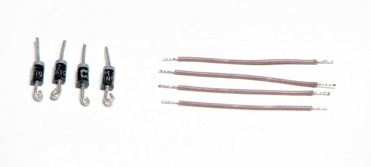 |
First, take the four diodes, cut both ends to about 1/2" (1 cm). Make a small loop in the anodes ends (the ones opposite the ends with the circle all the way around). Strip the wires back about 1/8" (1/2 cm), and twist & tin the wires. |
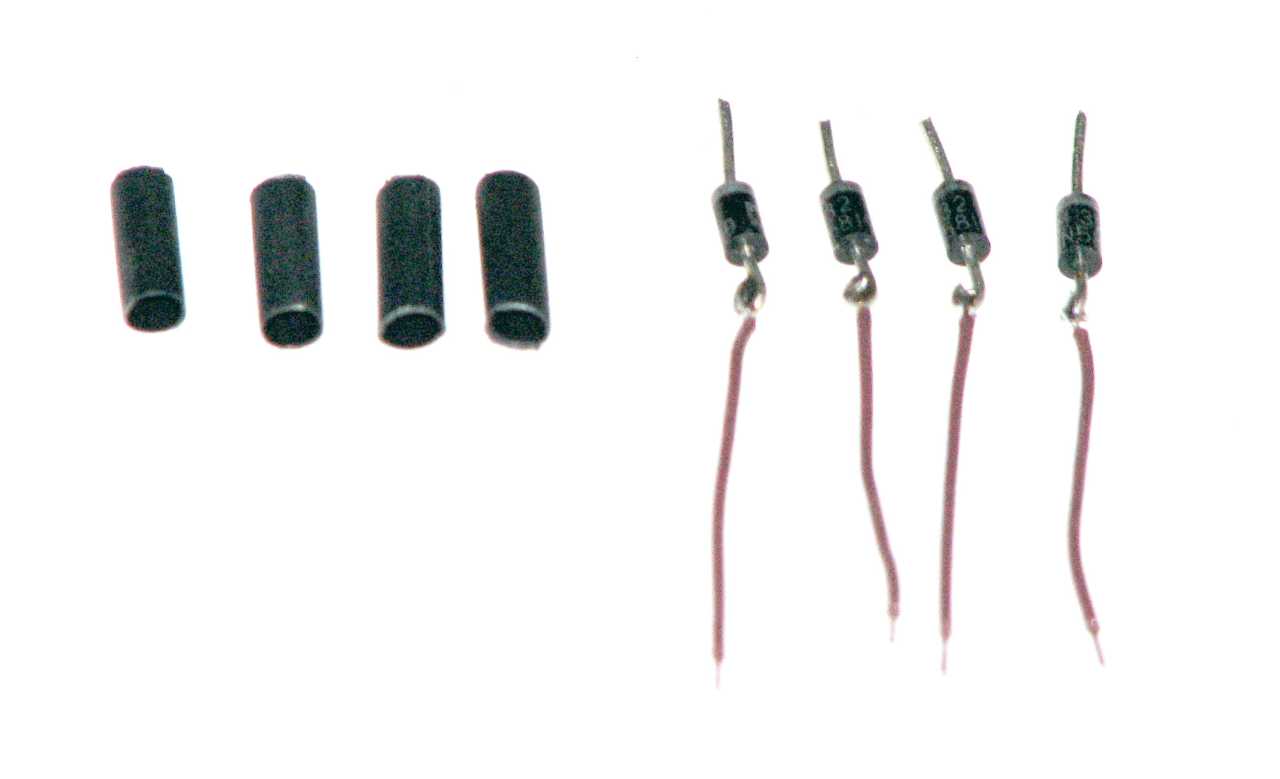 |
Second, make a loop in one end of each wire, hook it to the loop of one diode and solder the two together. Cut some 3/32" or 1/8" heat shrink tubing to about 1/2" (1 cm), enough length to cover the wire/diode solder joint and just go over the end of the diode. The heat shrink prevents the diode legs from shorting to each other when soldered to the DB25. |
 |
Third, place the heat shrink tubing over the solder joint and the end of the diode and shrink it on. The modules are now ready to be used. |
Step 2: Prep the DIN6 plug and attach the wires
- Pre-solder pins 2 to 6 on the DIN6 so that the wires will solder better
- Strip off one end of the 4 conductor cable about 1/2" (1.2 cm) back.
- Strip the individual wires back about 1/8" (3 mm) to expose bare wire.
- Twist and tin the wires and ground shield wire
- Solder these 5 conductors into the cups on pins 2 to 6 of the 6-pin round DIN plug, making sure the outer ground shield goes to pin 2 (GND). Mark down the wire colors going to each DIN post for later. Pin 1 on the DIN6 is not used. Soldering to these pins is not easy, and excess heat can cause the plastic to melt and cause the pin to shift.
- Fit the completed DIN end into its shield, crimp the cable into the tail clamp, and put the outer sheath over the shield, completing the DIN end.
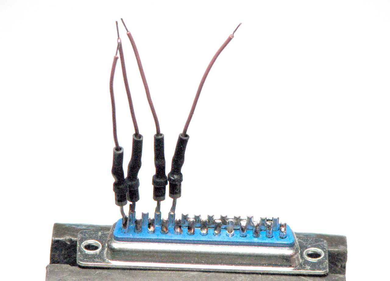
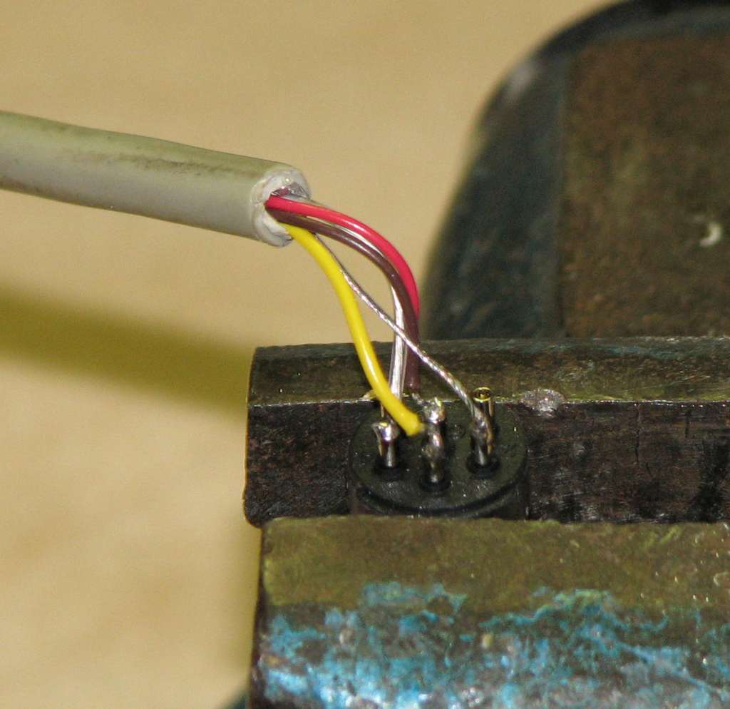 |
Wires attached to the DIN plug. |
Step 3: Prepare the DB25 connector and attach the diode modules
- Pre-solder the DB25 cups 10, 11, 12 & 13 so that the DIN6 wire insertion will be easier.
- Solder bridge pins 18 through 25 on the DB25 connector to make the ground strip.
-
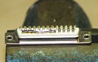
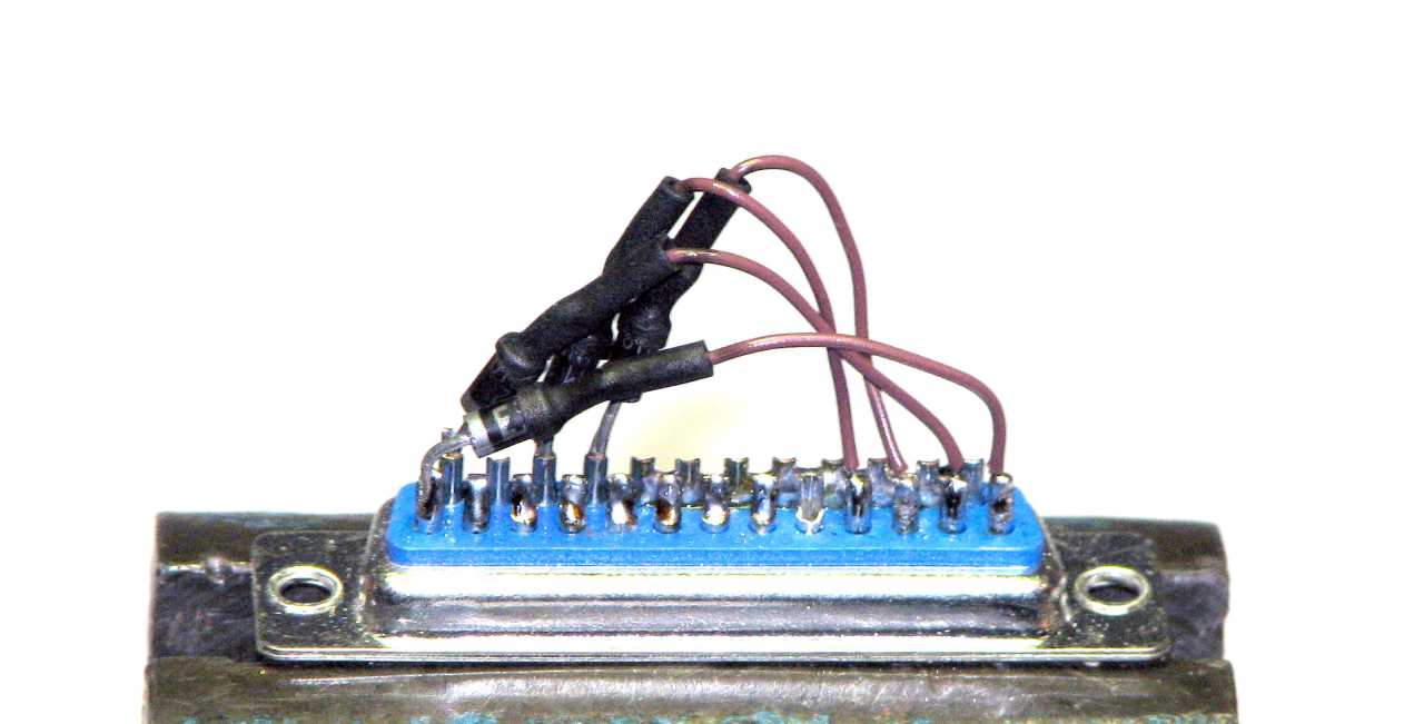
The solder bridge on the DB25 from pins 18 to 25. - Solder a diode (cathode end, the end of the diode without the wire attached) to the pins listed...
- 1
- 14
- 16
- 17
-

The diode modules on the DB25
- Now, bend the wires attached to the diodes and solder the wire to its appropriate pin listed...
- Diode anode to cathode on the DB25 pins... (cathode ---|<--- anode)
- 16 to 10
- 17 to 11
- 14 to 12
- 1 to 13
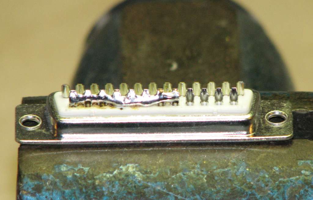
-
The diode modules completely soldered to the DB25
Step 4: Attach the wires from the DIN6 serial connector
- Strip the other end of the 4 conductor cable back about 3/4" (2 cm)
- Strip each wire back about 1/4" (5 mm) to expose bare wires
- Twist and tin the wires and ground shield wire
- Attach the wires from the 4 conductor cable to the DB25 pins, using the previous color code as a guide.
- DIN6 to DB25 pins...
- 2 to 25
- 3 to 13
- 4 to 12
- 5 to 10
- 6 to 11
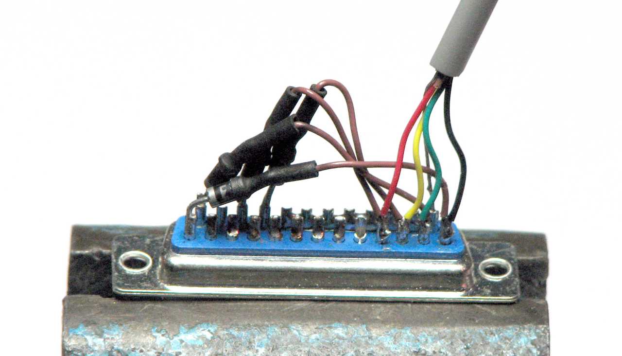
-

All the diode bridges in place, and the DIN6 serial cable is attached. The DB25 end is completed.
Step 5: Prep the DB15 connector and attach the wires
- Strip one end of the 8 conductor cable back about 3/4" (2 cm) to expose the wires.
- Strip each wire back about 1/4" (5 mm).
- Twist and tin each wire.
- Pre-solder each cup from pin 1 to 8, so that wire insertion will be easier.
- Attach the 8 wires to pins 1 to 8 on the DB15. Mark down what wire color goes to what pin, for later use.
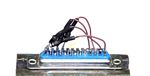
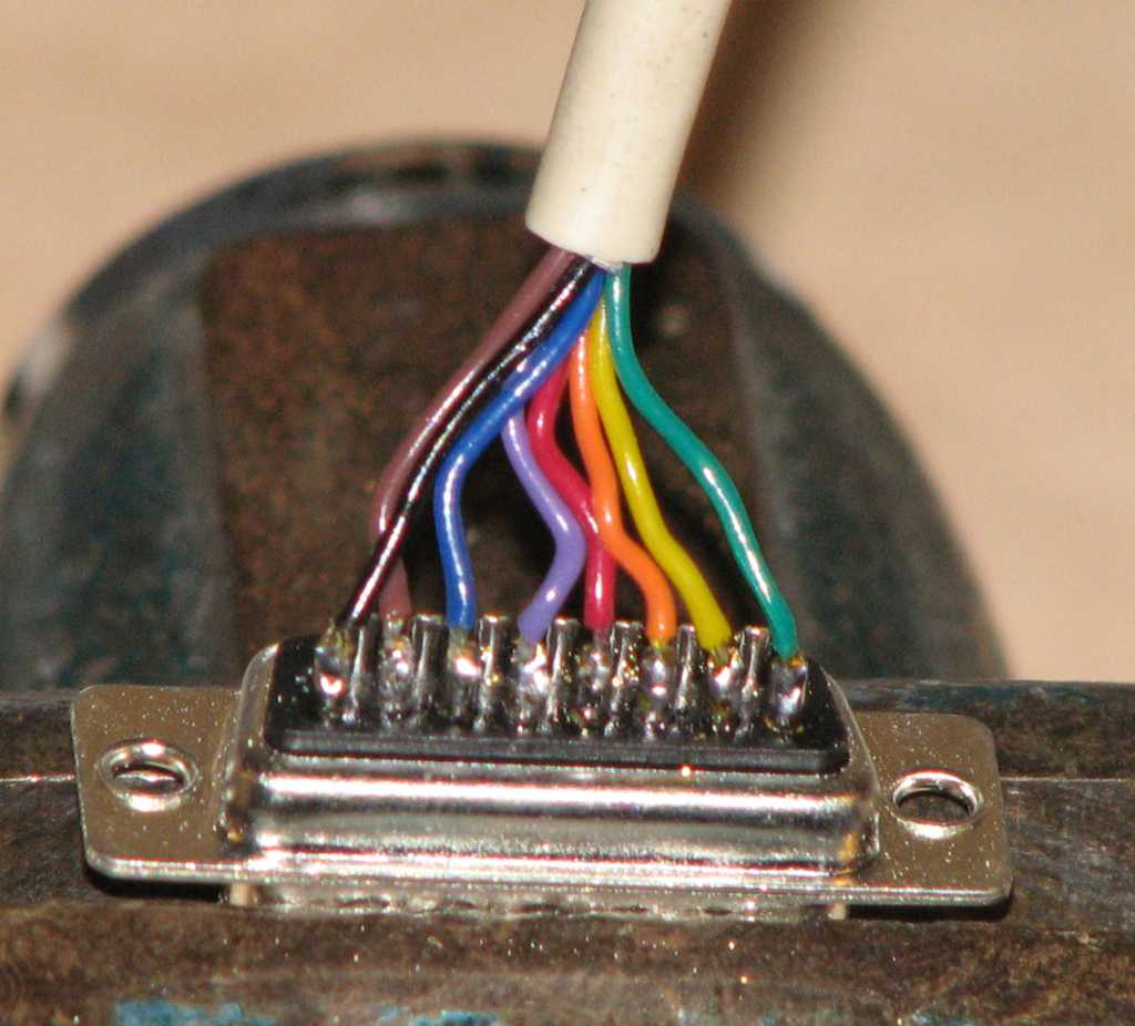 |
Wires attached to the DB15 |
Note that there is no ground line on this half of the cable. This is because the serial half contains the ground lines and an inclusion of a ground line here could cause a ground loop condition, something which must be avoided. Also, the parallel port add-on on the C= disk drive doesn't contain a ground line for this very reason.
Step 6: Prep the other end of the 8 conductor wire and attach to the DB25
- Strip the other end of the 8 conductor cable back about 3/4" (2 cm) to expose the wires.
- Strip each wire back about 1/4" (5 mm).
- Twist and tin each wire.
- Attach each wire to the DB25, using the color code from the previous step on the DB15.
- DB15 to DB25 pins...
- 1 to 2
- 2 to 3
- 3 to 4
- 4 to 5
- 5 to 6
- 6 to 7
- 7 to 8
- 8 to 9
 |
The completed DB25 end. Crowded with the diodes in there. |
Step 6: Check the cable
- Using a multi-meter on DIODE (continuity) check, measure between the pins on the following chart.
- DIN6 to DB25 wires
- DB15 to DB25 wires.
- DB25 diode bridges
- There should be a short between each of the pins from one connector to the other.
- For the diode bridges on the DB25, you must use the RED (+) lead on the ANODE end of the diode, and BLACK (-) lead on the CATHODE end in order to get a reading. There will not be a short, but rather a small diode drop from .3 to .7 volts.
- Verify that pins 18 through 25 on the DB25 are shorted together.
Cable pinout chart
DIN6 (male) |
DB15 (male) |
DB25 (male) |
|---|---|---|
2 (GND)
|
18-25 (GND)
|
|
3 (ATN)
|
13 (SELECT)
|
|
4 (CLK)
|
12 (PAPER END)
|
|
5 (DATA)
|
10 (ACK)
|
|
6 (RESET)
|
11 (BUSY)
|
|
1 (PB0) |
2 (DATA0) |
|
2 (PB1) |
3 (DATA1) |
|
3 (PB2) |
4 (DATA2) |
|
4 (PB3) |
5 (DATA3) |
|
5 (PB4) |
6 (DATA4) |
|
6 (PB5) |
7 (DATA5) |
|
7 (PB6) |
8 (DATA6) |
|
8 (PB7) |
9 (DATA7)
|
|
13 (SELECT) -->|-- 1 (STROBE)
|
||
12 (PAPER END) -->|-- 14 (AUTOFEED) |
||
11 (BUSY) -->|-- 17 (SELECTIN) |
||
10 (ACK) -->|-- 16 (INIT) |
||
18 to 25 shorted |
Step 7: Finish the cable. Mount the DB ends in their hoods
- Mount both the DB15 and the DB25 connectors in their respective hoods. If the diodes or wires need to be squished a bit to fit, it should be OK to do so.
- Test the cable to make sure it works.
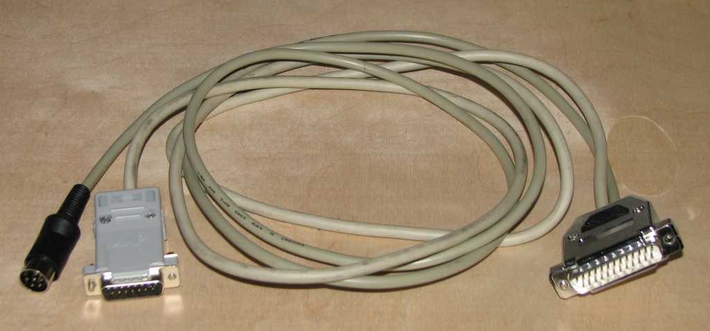 |
The completed XMP cable |
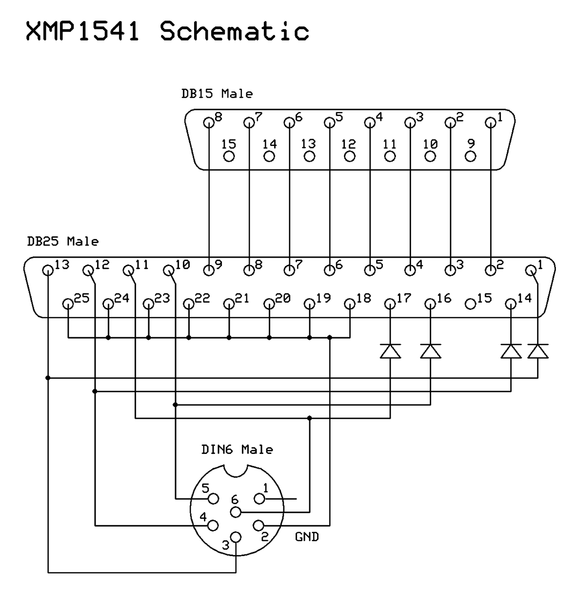 |
Schematics drawn using ExpressPCB, a free and excellent solution which also supports PC board layout editing.
Email the author: Peter Schepers | Last updated: June 8, 2009